
A coding machine base with an annular groove

A ring groove and coding machine technology, which is applied in printing, stamping, etc., can solve problems such as structural dislocation, inconsistent actions, and inaccurate dimensions, and achieve the effect of reasonable design, overcoming unreasonable design, and precise structure

Inactive Publication Date: 2011-12-21
平湖市电子有限公司
View PDF0 Cites 0 Cited by
  • Summary
  • Abstract
  • Description
  • Claims
  • Application Information

AI Technical Summary

Problems solved by technology

[0003] In order to overcome the deficiencies and defects of the coding machine in the prior art, such as unreasonable base design, inaccurate size, structural dislocation, improper installation, inconsistent actions, unclear typing and coding, etc., the present invention provides a The base of the coding machine, with reasonable design and precise structure, can make the coding machine clearly mark the production date and production batch on the plastic bottles and cartons of food cans or food plastic bags or beverages, medicines and other products. , shelf life, etc.

Method used


Image

  • A coding machine base with an annular groove
  • A coding machine base with an annular groove
  • A coding machine base with an annular groove

Examples


Embodiment Construction

[0010] The present invention will be further described below in conjunction with accompanying drawing:

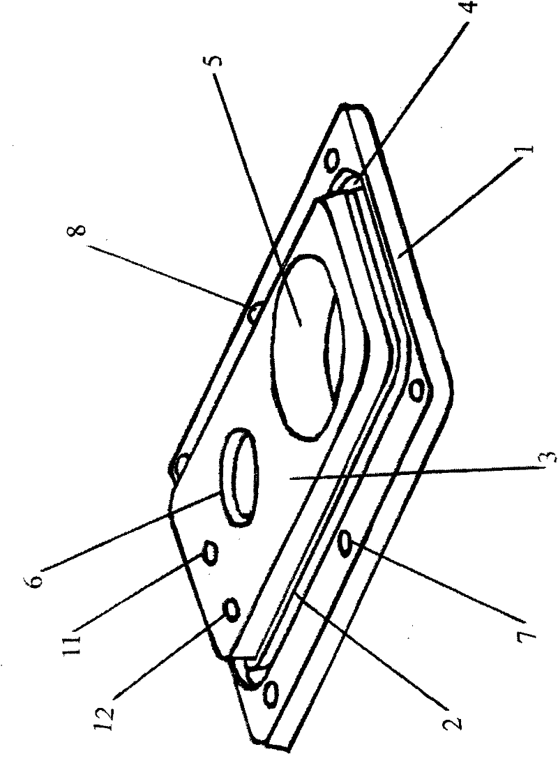
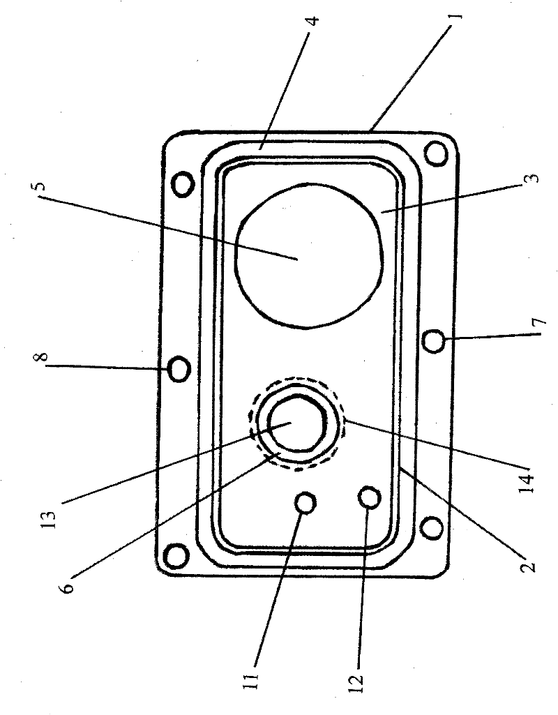
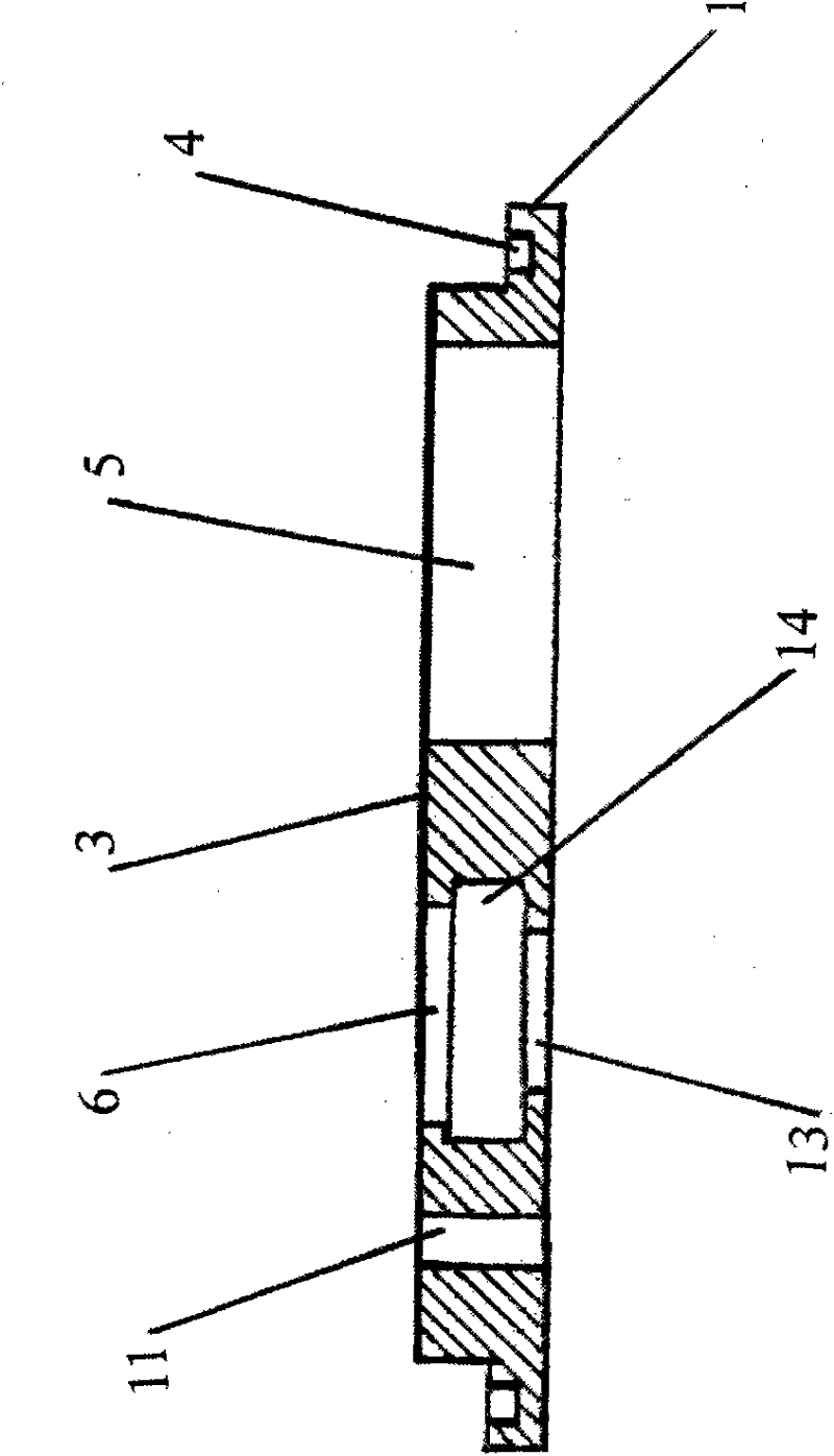
[0011]A coding machine base with an annular groove, including a base plate, a groove and a hole, characterized in that the base plate 1 is a rectangular parallelepiped metal plate, the left and right lengths of the base plate 1 are 95.25mm, and the front, The rear width is 61.9252mm, and the upper and lower heights are 3.9624mm; the base plate 1 has six sides, left, right, front, rear, upper and lower, and the left, right, front and rear corners of the base plate 1 are Small rounded corners, the radius of the four small rounded corners is 3.9624mm; there is an annular groove 4 on the top of the base plate 1, the annular groove 4 is a groove with a four-sided shape, and the depth of the annular groove 4 is 2.032mm mm, the width of the annular groove 4 is 1.1938mm, the annular groove 4 is surrounded by the outer ring edge and the inner ring edge, the annular groove 4 is conne...


PUM


Abstract

The invention discloses a coding machine base with an annular groove. The base plate is a rectangular parallelepiped metal plate with four small rounded corners. An annular groove is opened on the base plate, consisting of a front groove, a right groove, a rear groove, The left groove is connected, and the four corners of the outer ring edge of the annular groove are large rounded corners, and the four corners of the inner ring edge are medium rounded corners; on the base plate: three front through holes, left, middle and right, are set in front of the front groove , There are three rear through holes on the left, middle and right behind the rear groove, and a convex plate is set in the annular groove, which is connected with the base plate, and the center of the convex plate coincides with the center of the base plate; above the convex plate: the right part of the convex plate Drill a large through hole, drill the upper hole on the left side of the large through hole, the middle hole under the upper hole, and the lower hole under the middle hole are all concentric circles; on the convex plate: drill the rear threaded hole on the left side of the upper hole, which is a through hole Drill the front threaded hole in front of the rear threaded hole, which is a through hole; under the base plate: Drill four small threaded holes in the left front, left rear, right front and right rear direction of the large through hole, and drill in the left front and right rear direction of the lower hole Drill a total of two large threaded holes.

Description

technical field [0001] The invention relates to a coding machine base with an annular groove, in particular to a coding machine base with an annular groove so that the coding machine can clearly print on food cans or food plastic bags or beverages, medicines and other products. Plastic bottles, cartons and other materials are marked with production date, production batch, shelf life and other words. Background technique [0002] Usually, due to unreasonable design, inaccurate size, misaligned structure, improper installation, inconsistent actions, etc., the machine base of the coding machine cannot clearly print on food cans or food plastic bags or beverages, medicines and other products. Plastic bottles, cartons and other materials are marked with the date of production, production batch, shelf life, etc., resulting in blurred handwriting, missing strokes, or even no words, seriously affecting the commercial image and sales market. Contents of the invention [0003] In o...

Claims


Application Information

Patent Timeline
Patent Type & Authority Applications(China)
IPC IPC(8): B41K3/62
Inventor 林正其林丽君
Owner 平湖市电子有限公司
Learn More