
Tension pay-off device for wire rope

The technology of a pay-off device and a wire rope is applied in the field of the pay-off device, which can solve the problems of unstable tension and the like, and achieve the effects of convenient installation and regulation and simple structure.

Inactive Publication Date: 2011-12-21
陈建文
View PDF9 Cites 14 Cited by
  • Summary
  • Abstract
  • Description
  • Claims
  • Application Information

AI Technical Summary

Problems solved by technology

And the usual solution is: change the pay-off reel from the passive wheel to the driving wheel, and with this the rotating speed of the driving wheel is synchronous (consistent) with the rotating speed of the take-up reel; but this method can only improve a certain tension on the wire rope Size, because firstly, the active rotation speed of the pay-off reel and the take-up reel cannot be synchronized, and their respective rotation speeds will be affected by various factors, such as the speed of pay-off, the amount of pay-off and other factors; During the transmission process, it will generate a changing tension, that is, the tension of the transmission movement is different and changing on the whole rope, which will lead to the instability of the whole tension

Method used


Image

  • Tension pay-off device for wire rope
  • Tension pay-off device for wire rope

Examples


Embodiment Construction

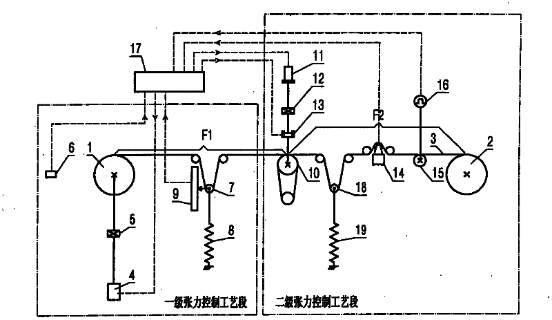
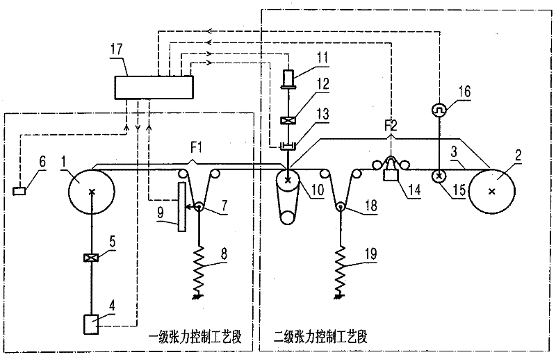
[0015] The present invention will be described in detail below in conjunction with accompanying drawing: figure 1 As shown, the present invention includes a pay-off reel 1 and a take-up reel 2 and a wire rope 3 wound on the pay-off reel 1 and the take-up reel 2 respectively, wherein the take-up reel 2 winds the wire rope 3 at a certain speed On the driving wheel thereon, a primary tension F1 is produced on the wire rope 3 behind the pay-off reel 1, and a secondary tension F2 is generated on the wire rope 3 before the take-up reel 2; the pay-off reel 1 The wheel shaft is provided with a first-stage pay-off power mechanism 4 that controls the primary tension F1 of the wire rope through torque or speed; on the wire rope 3 in front of the pay-off reel 1, there is a coil that can control the wire rope through the output torque or speed. Secondary pay-off wheel set 10 with secondary tension F2.

[0016] The first-level pay-off power mechanism 4 is at least composed of a speed-adjus...


PUM


Abstract

A tension wire pay-off device for a wire rope, the device includes a wire pay-off reel and a wire take-up reel, and wire ropes wound on the pay-off reel and the wire take-up reel respectively, wherein the wire take-up reel winds the wire rope at a certain speed On the driving wheel on it, a primary tension is produced on the wire rope after the pay-off reel, and a secondary tension is generated on the wire rope before the take-up reel; the axle of the pay-off reel is provided with a passing torque Or a primary pay-off power mechanism whose speed controls the primary tension of the wire rope; a secondary pay-off wheel group capable of controlling the secondary tension of the wire rope through the output torque or speed is coiled on the wire rope before the pay-off reel; It effectively solves the problems of large tension and unstable transmission in the wire rope transmission process in the pay-off device. It has the characteristics of simple structure, convenient installation and control, and can make the wire rope transmission run safely under high precision and constant tension state.

Description

technical field [0001] The invention relates to a wire pay-off device for constant tension control of wire ropes, and belongs to the technical field of wire rope winding transmission. Background technique [0002] In the prior art, the transmission and winding process of the wire rope or the wheel belt is mainly between the pay-off reel and the take-up reel, and is driven by the take-up reel after winding the pay-off reel and the take-up reel; usually Next, the take-up reel is an active roulette, driven by the tension of the wire rope, it drives the pay-off reel to passively rotate and pay off the wire, so as to realize the wire take-up transmission process of the wire rope on the take-up reel, and during this process, the wire on the wire rope There is often a large tension force, and this tension force is constantly changing during the transmission process of the whole wire rope. This constantly changing tension force will affect the tension of the wire rope in some workpl...

Claims


Application Information

Patent Timeline
IPC IPC(8): B65H59/38
Inventor 陈建文
Owner 陈建文
Learn More