A boom machine that drives the translation of the reel

A technology of boom machine and driving machine, which is applied in the direction of clockwork mechanism and hoisting device, which can solve the problems of slipping out of the chute, danger, etc., and achieve the effect of ensuring safety

Inactive Publication Date: 2011-12-21
GUANGZHOU GREED ENG MACHINERY
View PDF4 Cites 35 Cited by
  • Summary
  • Abstract
  • Description
  • Claims
  • Application Information

AI Technical Summary

Problems solved by technology

[0003] In general, the sling (03) will run vertically within the distance between the pulley (02) and the drum (13), so as to ensure the distance between the sling (03), the pulley (02) and the drum (13). Stable work, but if the vertical distance between the reel (13) and the pulley (02) of the traditional boom machine is too short, when the sling (03) wound on the reel (13) is released to Figure 7 the last lap shown, then the sling (03) will happen as Figure 7 In the case of a large angle of deviation from the vertical position shown, the sling (03) may slip out of the chute on the pulley (02) and the drum (13) and a dangerous situation will occur

Method used


Image

  • A boom machine that drives the translation of the reel
  • A boom machine that drives the translation of the reel
  • A boom machine that drives the translation of the reel

Examples


Embodiment Construction

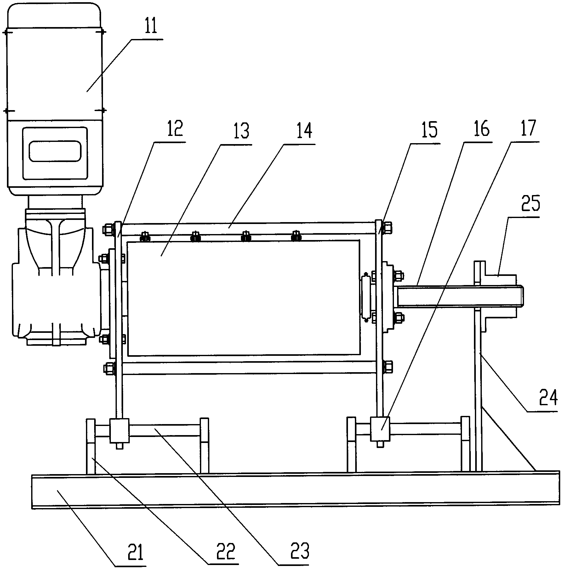
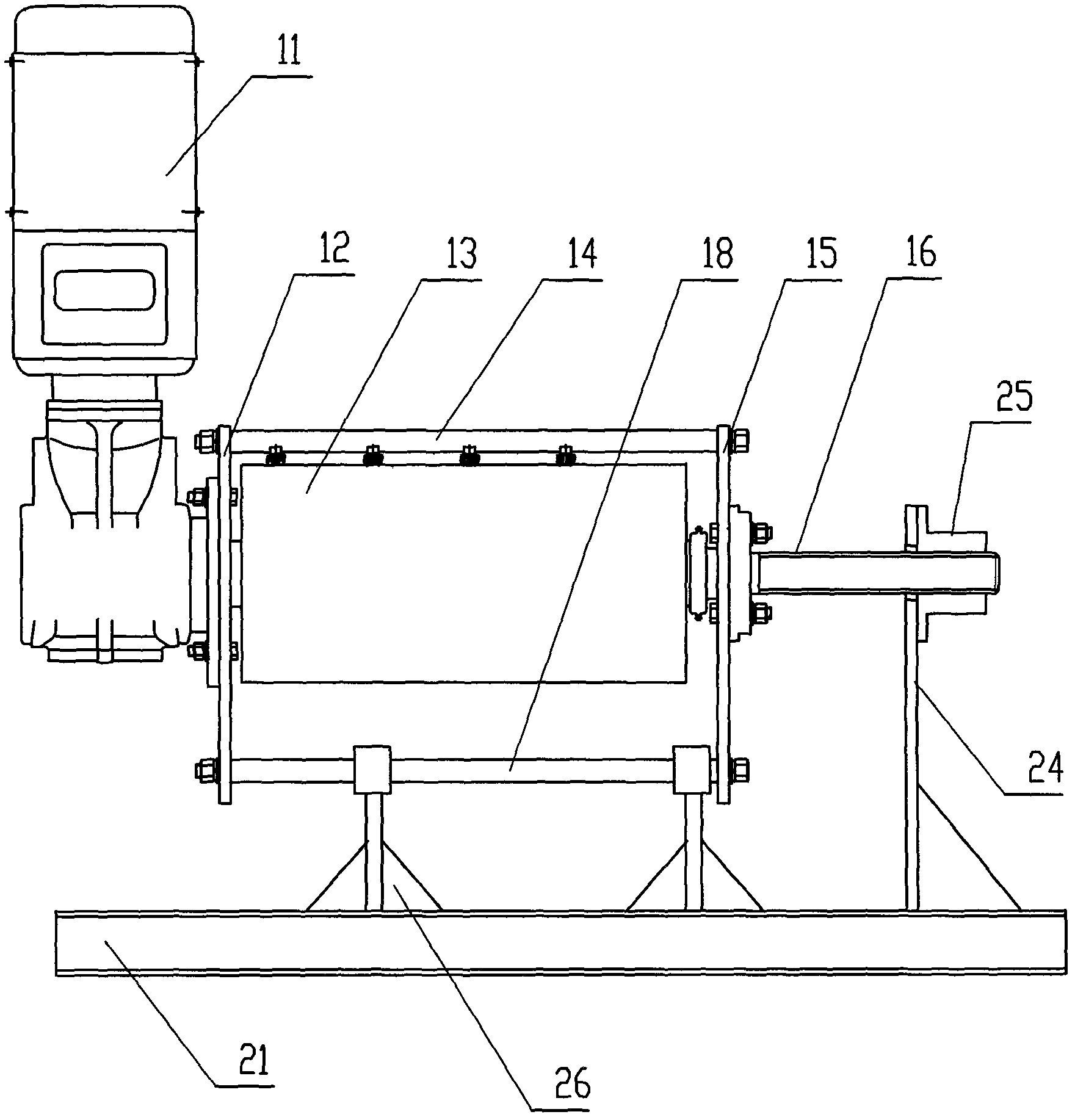
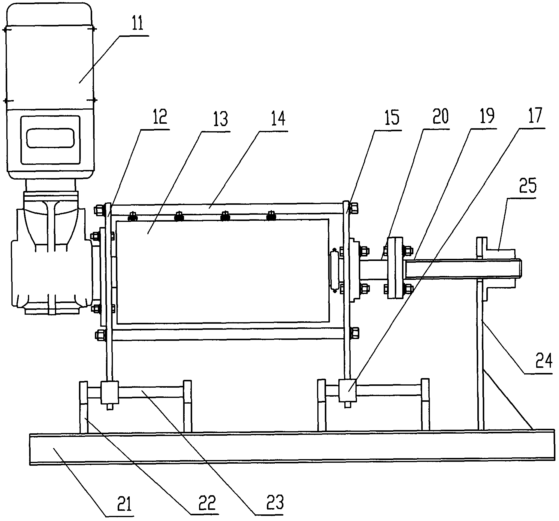
[0020] figure 1 The present invention uses the screw reel shaft (16) to pull the movable part of the boom machine driver to move, and sets the slide bar (23) on the base (21) to ensure that the sling (03) keeps the original position downward from the pulley (02). Schematic diagram of the structure in the vertical state.

[0021] figure 1 Among them, the screw drum shaft (16) is driven by a motor and a reducer (11), and the front drum support plate (15) and the rear drum support plate (12) support the screw drum shaft (16) and The drum (13) is provided with a sliding sleeve mechanism (17) at the lower part of the front drum support plate (15) and the rear drum support plate (12); the above structures 11-17 form the movable part of the boom machine driver The base (21) is provided with a slide bar support plate (22) to support the slide bar (23), and the linear bearing in the sliding sleeve mechanism (17) slides along the slide bar (23); There is a base support plate (24), ...


PUM


Abstract

The invention discloses a boom machine for driving a reel to translate. The motor and reducer of the boom machine driving machine, the front reel support plate, the rear reel support plate, the pull rod, the reel and the reel shaft are designed into one A whole that can move relative to the base; a screw rod is set at one end of the reel shaft to match with a tension nut set on the base through a support plate. When the motor and reducer drive the reel shaft to rotate, due to the coordinated movement between the screw on the movable reel shaft and the tension nut fixed on the base, the reel of the boom machine driver and its reel are pulled. The movable integral part such as the cylinder shaft performs translational movement relative to the base, so that the sling is always kept in a state perpendicular to the pulley.

Description

Technical field [0001] The invention relates to a boom machine which drives a reel to move in translation. Background technique [0002] The working principle of the traditional boom machine is as follows: Figure 6 and Figure 7 Shown: motor and reducer (11) drive traditional reel shaft (05), and traditional reel shaft (05) drives reel (13); One end of sling (03) is fixed on the reel (13), and then Wrap around the reel (13) in a circle, and the other end goes down through the pulley (02), and the arrow end is the load to be lifted, such as the stage screen boom and so on. [0003] In general, the sling (03) will run vertically within the distance between the pulley (02) and the reel (13), so as to ensure the distance between the sling (03), the pulley (02) and the reel (13). Stable work, but if the vertical distance between the reel (13) and the pulley (02) of the traditional boom machine is too short, when the sling (03) wound on the reel (13) is released to the Figure...

Claims


Application Information

Patent Timeline
Patent Type & Authority Applications(China)
IPC IPC(8): B66D1/39
Inventor 陈德荣
Owner GUANGZHOU GREED ENG MACHINERY
Why Eureka
Try Eureka