light box

A light box and box body technology, applied in the field of decorative lighting, can solve problems such as high cost and increased energy consumption of light boxes, and achieve the effects of cost reduction, total power reduction, and number reduction.

Inactive Publication Date: 2011-12-21
RISHANG OPTOELECTRONICS
View PDF10 Cites 2 Cited by
  • Summary
  • Abstract
  • Description
  • Claims
  • Application Information

AI Technical Summary

Problems solved by technology

To install the LED light-emitting module, it is necessary to install an auxiliary mounting plate similar in size to the light-emitting surface of the light box in the light box, and then install the LED light-emitting module on the auxiliary mounting plate, and the

Method used


Image

  • light box
  • light box
  • light box

Examples


Embodiment Construction

[0025] In order to solve the problem of high energy consumption of the existing lighting light box, a technical improvement scheme of a new light box is proposed.

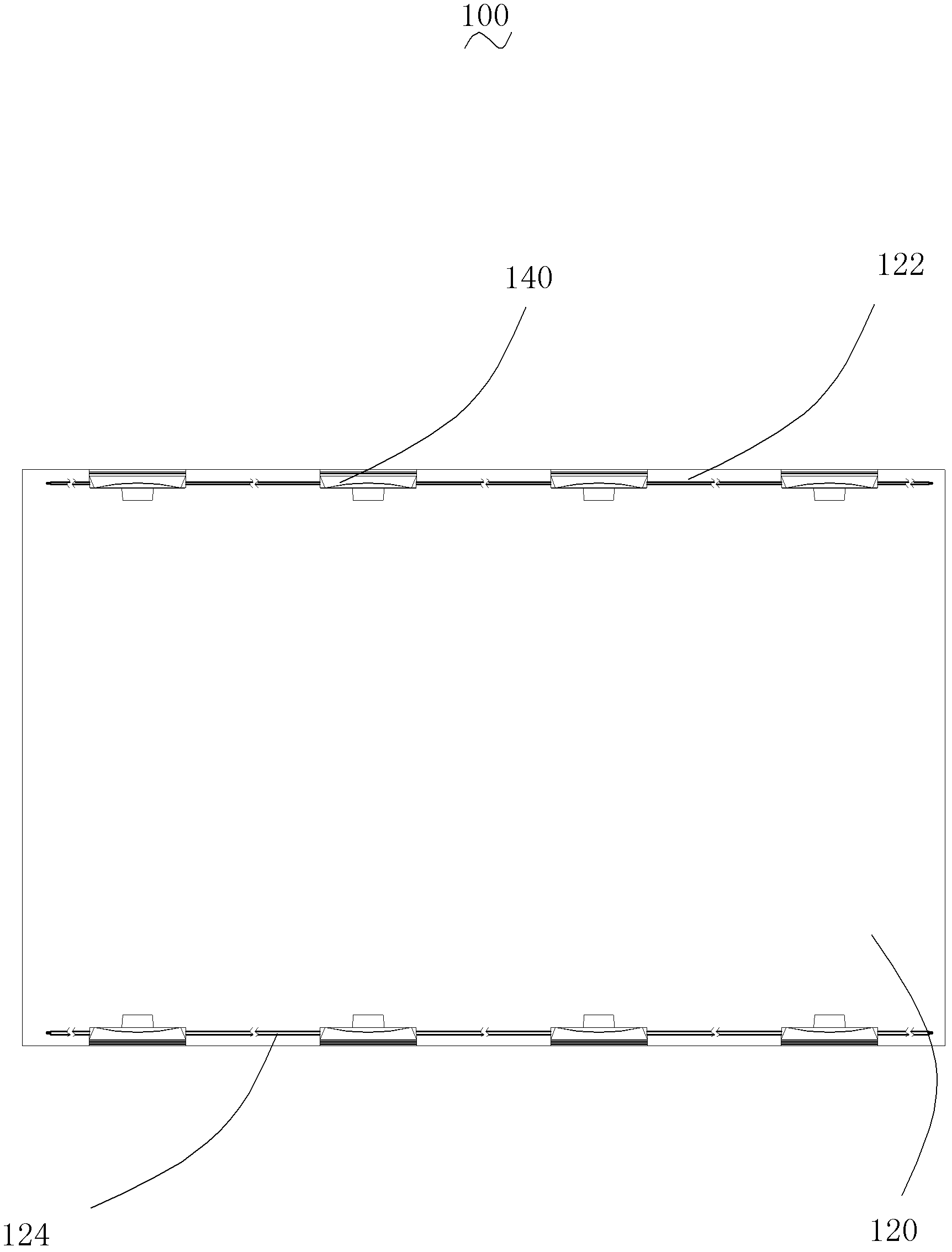
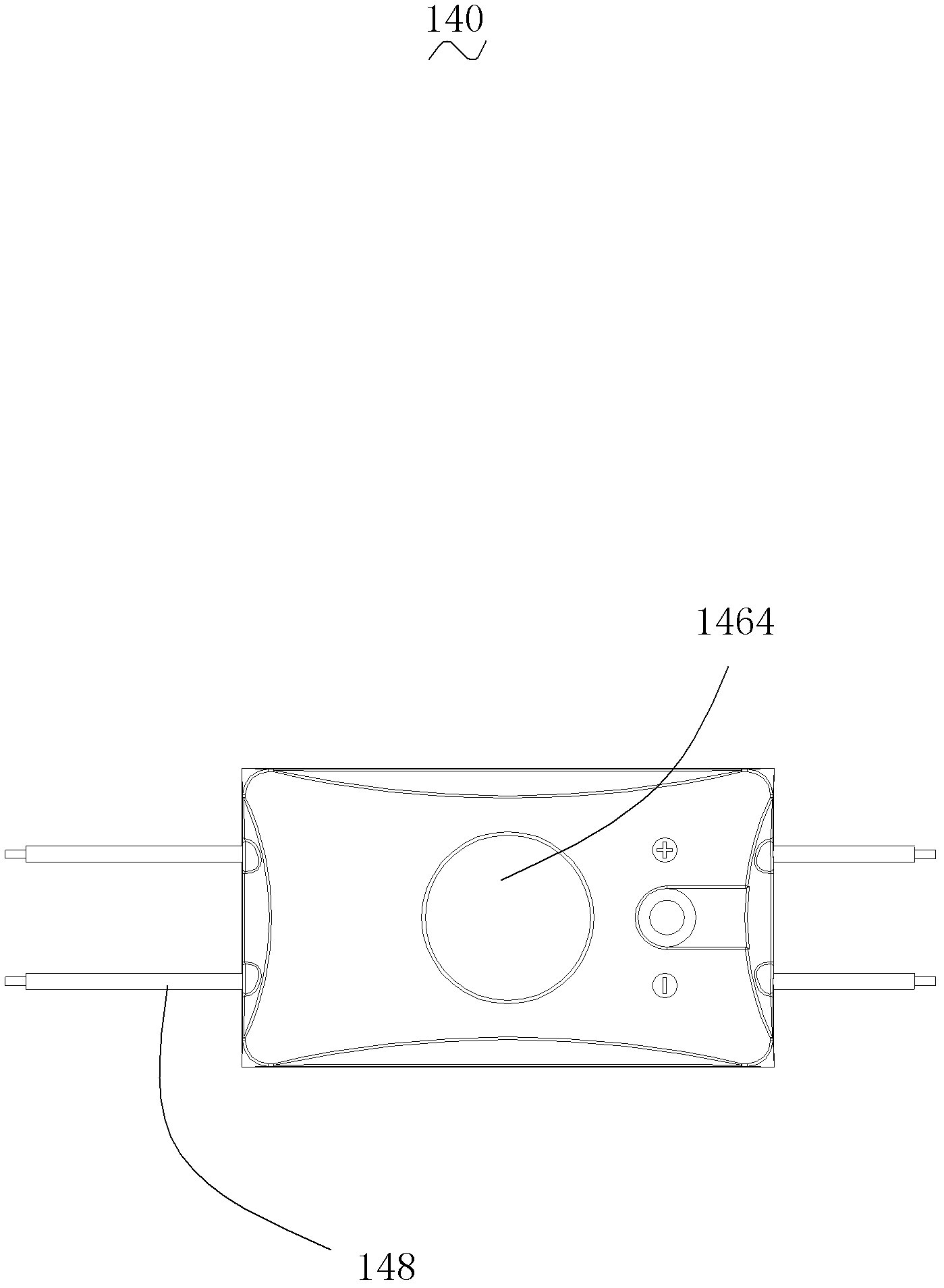
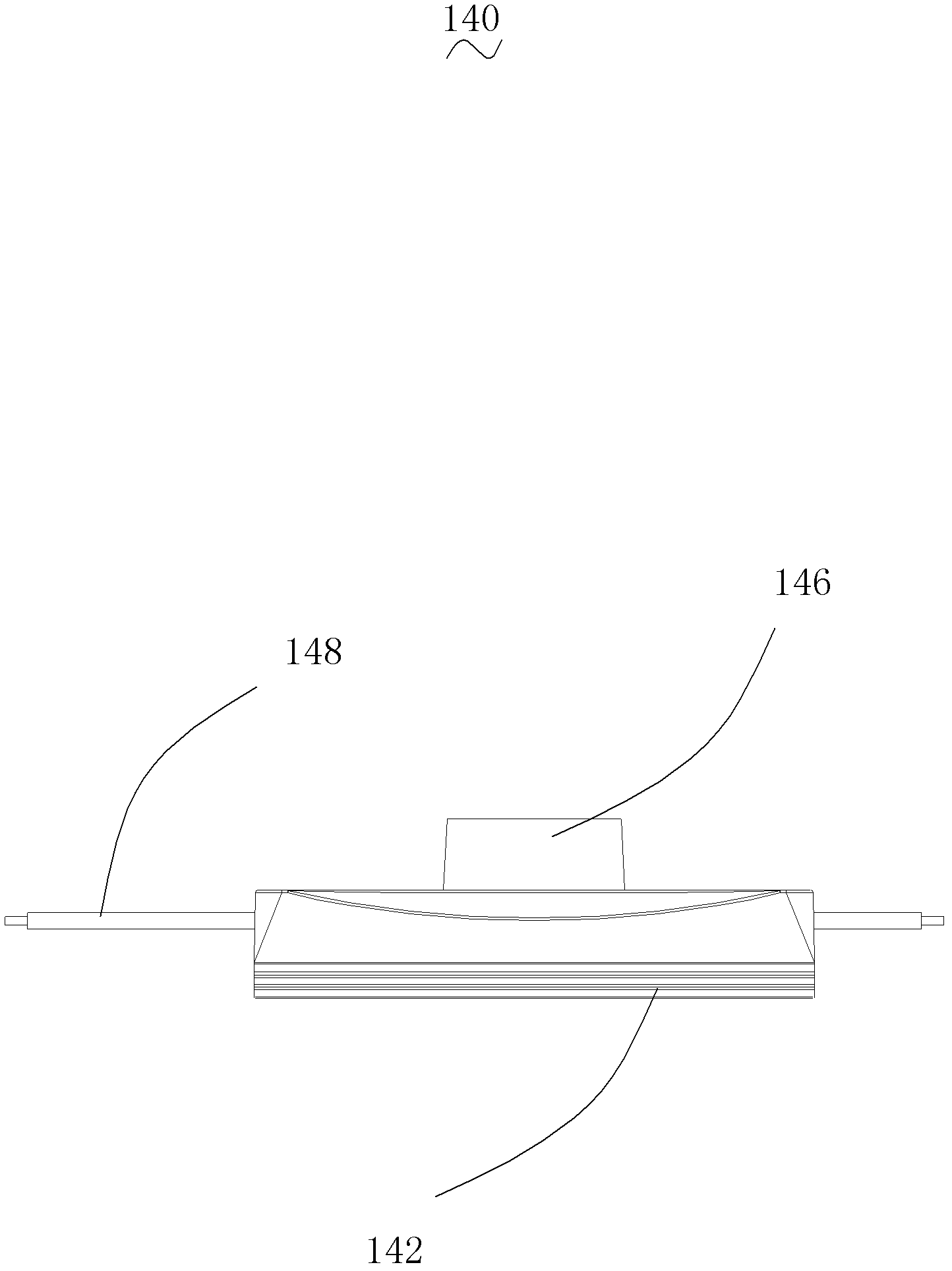
[0026] Such as figure 1 As shown, the light box 100 of this embodiment includes a box body 120 having at least one light-emitting surface and light source assemblies 140 symmetrically disposed on two opposite sides of the box body 120 close to the light-emitting surface. The illumination directions of the two light source assemblies 140 are opposite to each other.

[0027] In this embodiment, the box body 120 is a cuboid structure with two opposite light-emitting surfaces, and the distance from the light source assembly 140 to the two light-emitting surfaces is equal. The distance between the two light emitting surfaces is the thickness of the box body 120 , and the distance between two opposite sides of the box body 120 where the light source assembly is disposed is the width of the box body 120 . The thickness ...


PUM


Abstract

The invention relates to a light box, comprising a light source assembly and a box body with at least one light-emitting surface, the light source assembly includes a light source, and the light source assembly is symmetrically arranged on two opposite sides of the box body close to the light-emitting surface, and The direction of illumination is opposite, and it is characterized in that, the light source assembly also includes a light concentrating module covering the light source; the light concentrating module includes a light shield with a light exit hole and a lens accommodated in the light exit hole, and the lens will The light emitted by the light source assembly converges into a cone-shaped illumination light path, and the apex angle of the cone-shaped illumination light path is α, which satisfies the relationship tgα/2=L/H; wherein, L is the distance between the light source assembly and the light-emitting surface. The distance between them, H is half of the distance between the two opposite sides. The cost and energy consumption of the above light box are relatively low.

Description

【Technical field】 [0001] The invention relates to a decorative lighting fixture, in particular to a light box. 【Background technique】 [0002] The light box is a common decorative lighting fixture, which is mostly used in the field of advertising and guiding lighting. Usually when in use, text, patterns, etc. are printed on the light-emitting surface, and then energized to emit light, thereby producing a visually significant lighting effect. [0003] The light source that the light box in the traditional technology mostly adopts is a fluorescent tube. The color of fluorescent tubes is relatively single, and the light often has high-frequency flickering. As a light source for advertising and guidance, it cannot achieve the desired effect. The fluorescent tube has high working power and short service life, which wastes electricity and requires the user to frequently replace the lamp tube, thereby increasing the user's use cost. [0004] There are also many light boxes in th...

Claims


Application Information

Patent Timeline
IPC IPC(8): F21S2/00F21V19/00F21Y101/02
Inventor 梁俊
Owner RISHANG OPTOELECTRONICS
Why Eureka
Try Eureka