
Clamping mechanism of charge-discharge test device for thin secondary battery

A secondary battery and test device technology, which is applied in secondary battery charging/discharging, secondary battery testing, secondary battery, etc., can solve problems such as cumbersome installation, poor workability, and inability to clamp, so as to reduce cumbersome operations, Effect of reducing workload and improving clamping accuracy

Active Publication Date: 2011-12-21
TOKYO SEIMITSU +1
View PDF9 Cites 12 Cited by
  • Summary
  • Abstract
  • Description
  • Claims
  • Application Information

AI Technical Summary

Problems solved by technology

[0006] Moreover, although the charge-discharge test device 9 can perform a charge-discharge test on a plurality of thin secondary batteries 1 at a time, the thin secondary batteries 1 (electrode terminals 5, 7) are attached to a plurality of clip-type connection terminals 11 groups. very cumbersome
[0007] Furthermore, since the charge-discharge stand 13 provided with the connection terminal 11 group is integrated with the charge-discharge test device 9, it has been pointed out that the charge-discharge test is limited by the place and the entire device is enlarged.
[0008] In addition, in the conventional example disclosed in Japanese Patent Application Laid-Open No. 2004-319334, although it is also possible to conduct a charge-discharge test on a plurality of thin secondary batteries at one time, there is a need to store and arrange the plurality of thin secondary batteries before the test. The work in the battery storage container has poor workability
[0009] However, on the other hand, if there is no structure for fixing the thin secondary battery like the battery storage container, the position of the electrodes of the thin secondary battery may become irregular during the charge-discharge test, and Risk of not being able to clamp with high precision

Method used


Image

  • Clamping mechanism of charge-discharge test device for thin secondary battery
  • Clamping mechanism of charge-discharge test device for thin secondary battery
  • Clamping mechanism of charge-discharge test device for thin secondary battery

Examples


Embodiment Construction

[0043] Hereinafter, embodiments of the present invention will be described in detail based on the drawings.

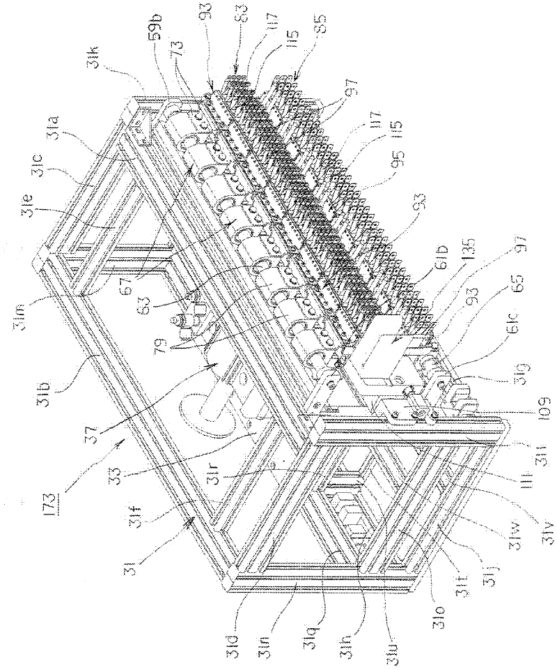
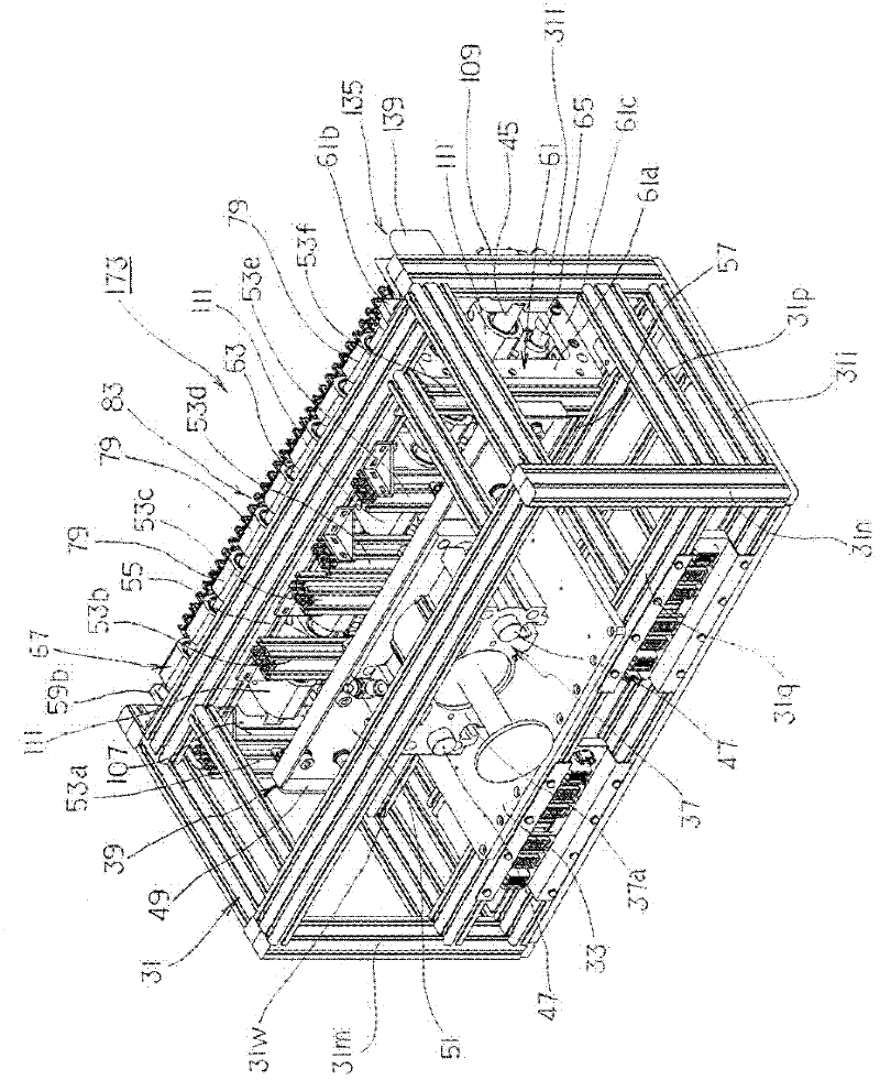
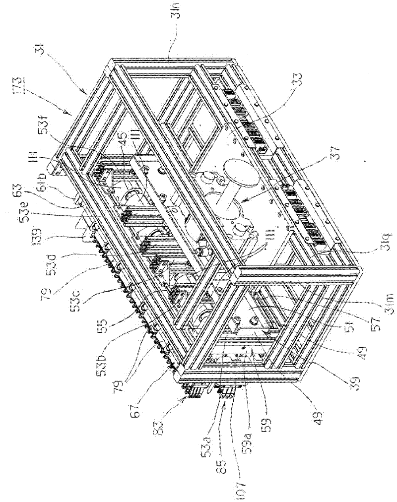
[0044] Figure 1 to Figure 12 The clamping mechanism of the charge-discharge test device for a thin secondary battery according to an embodiment of the present invention is shown. Figure 1 to Figure 5 Among them, 31 is a support base composed of a rectangular parallelepiped frame formed by a plurality of pillars 31 a to 31 w arranged in front, rear, left, and right sides, as figure 1 as well as figure 2As shown, between the pillars 31w spanning between the left and right side pillars 31o, 31p and the pillars 31q spanning between the left and right rear pillars 31m, 31n, a mounting plate 33 having a rectangular shape in plan view is attached. An air cylinder (drive unit) 37 is installed on the loading plate 33, and the air cylinder 37 makes Figure 6 to Figure 9 The illustrated piston rod 35 expands and contracts in the front-rear direction of the support base 31 ...


PUM


Abstract

The present invention relates to a chuck mechanism of a charge / discharge testing device for flat-rechargeable batteries and has a proposition to provide a chuck mechanism that makes it possible to lighten conventionally needed troublesome works, that is, for example, works of storing and fixing a large number of flat-rechargeable batteries in a container, and that is capable of surely chucking the flat-rechargeable batteries (electrodes). The chuck mechanism includes a first guide couplable with a battery storage retaining a plurality of flat-rechargeable batteries arranged in parallel, and a plurality of chuck units continuously joined with the first guide and resiliently arranged in parallel, wherein the chuck units each have a second guide resiliently positioning each of the chuck units with a predetermined number of corresponding flat-rechargeable batteries in the battery storage.

Description

technical field [0001] The present invention relates to a clamping mechanism for an electrode terminal used in a charge-discharge test device for a thin plate-shaped secondary battery. Background technique [0002] formed as Figure 23 as well as Figure 24 The illustrated thin plate-shaped secondary battery 1 is used in many technical fields. The thin secondary battery 1 has a structure in which a pair of sheet-shaped electrode terminals 5 and 7 protrude from a flat case 3 in one direction. [0003] Moreover, like the conventional secondary battery, the thin secondary battery 1 is also manufactured in a factory and subjected to quality checks of charging and discharging tests a number of times, and the acceptable ones are shipped as products after being half-charged. [0004] Figure 25 A charge-discharge test device for a thin secondary battery disclosed in Japanese Patent Application Laid-Open No. 2000-58135 is shown. The charge-discharge test device 9 includes: a charg...

Claims


Application Information

Patent Timeline
Patent Type & Authority Applications(China)
IPC IPC(8): H01M10/44H01M50/209
CPCH01M10/4285H01M10/4207G01R31/3641H01M2/20G01R31/3658H01M2/1061H01R13/24Y02E60/12G01R31/3865Y02E60/10H01M50/209Y02P70/50
Inventor 西原孝川崎高裕冈崎勉八十冈武志波部宏朗丹羽良和
Owner TOKYO SEIMITSU
Learn More