A switchgear valve mechanism

A technology of switch cabinets and valves, which is applied in the direction of switchgear components, etc., can solve the problems of contact arm and base of the handcart and the valve plate, contact between the base of the handcart and the valve plate, and small effective stroke of the valve drive, etc., to achieve Good self-resetting, preventing left and right sliding, small transmission gap

Active Publication Date: 2011-12-21
SHANDONG TAIKAI COMPLETE ELECTRIC APPLIANCE
View PDF6 Cites 7 Cited by
  • Summary
  • Abstract
  • Description
  • Claims
  • Application Information

AI Technical Summary

Problems solved by technology

[0004] The valve drive of the existing center-mounted circuit breaker handcart is an arc-shaped chute structure, and the effective stroke of the valve drive is very small. It is difficult for the conventional valve mechanism to convert this stroke into the stroke of the opening and closing valve.
At the same time, the distance between the contact arm and base of the center-mounted circuit breaker handcart and the contact box is small, and it is easy to collide with the contact arm and base of the handcart when using a conventional folding valve; The base of the handcart collides with the valve plate, causing deformation of the valve, which poses a safety hazard

Method used


Image

  • A switchgear valve mechanism
  • A switchgear valve mechanism
  • A switchgear valve mechanism

Examples


Embodiment Construction

[0014] The present invention will be further described below in conjunction with accompanying drawing:

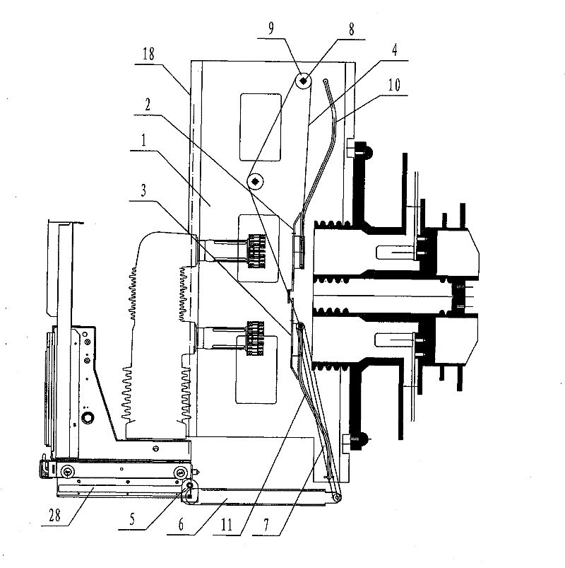
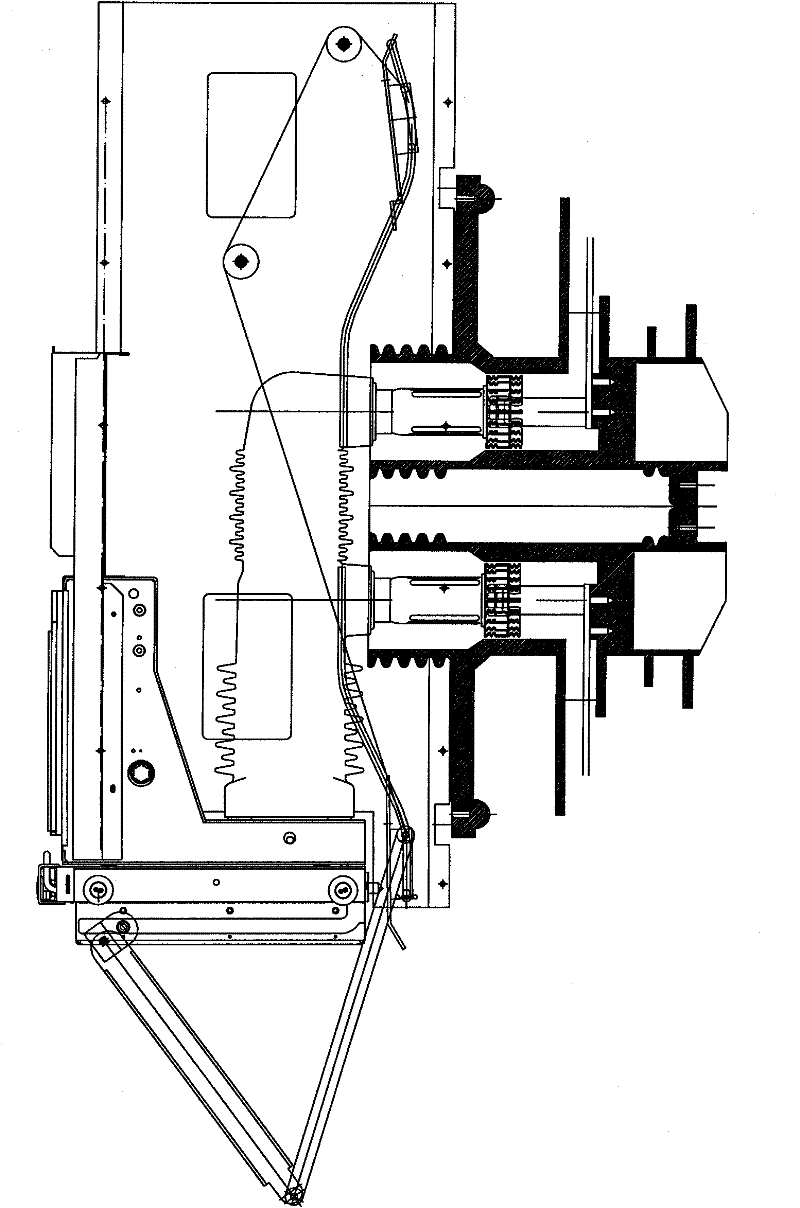
[0015] Such as figure 1 , 2 As shown in and 4, the left end of the valve connecting rod 6 is fixedly connected to the transmission mechanism 5, and its right end is hinged to the lower end of the small connecting rod 7, and the upper end of the small connecting rod 7 is hinged on the top of the lower valve plate 3, and the valve chute plate 1 is fixed on the cabinet body On the side wall 18, the top of the valve chute plate 1 is provided with a fixed shaft 8, the pulley 9 is set on the fixed shaft 8, the upper and lower parts of the valve chute plate 1 are respectively provided with an upper chute 10 and a lower chute 11, and the upper chute The groove width of each part of 10 is the same, the shape of the groove of the lower part is a vertical straight line, and the shape of the groove of the rest part is an arc-shaped curve extending upward, the shape of the lower groove...


PUM


Abstract

The invention discloses a switch cabinet valve mechanism. The left end of a valve connecting rod is fixedly connected with a drive mechanism. The right end of the valve connecting rod is hinged with the lower end of a small connecting rod. The upper end of the small connecting rod is hinged at the upper part of a lower valve plate. A valve sliding groove plate is fixed on the side wall of a cabinet body. A fixing shaft is arranged at the upper part of the valve sliding groove plate. A fixed pulley is arranged on the fixing shaft. An upper sliding groove and a lower sliding groove are respectively arranged at the upper part and the lower part of the valve sliding groove plate. One ends of pins are respectively hinged at the upper part and the lower part of the external side surface of an upper valve plate. One ends of pins are also respectively hinged at the upper part and the lower part of the external side surface of the lower valve plate. The other ends of the pins are socket-connected into corresponding rollers. One end of a steel wire rope is fixed at the upper end of the small connecting rod and the other end of the steel wire rope is wound through the fixed pulley and is fixed at the upper part of the upper valve plate. The switch cabinet valve mechanism has the characteristics of convenience in installation, firm fixation, high structural strength, good drive performance and the like, and is suitable for all kinds of switch cabinets.

Description

technical field [0001] The invention relates to a shutter mechanism of a switch cabinet. Background technique [0002] The switchgear valve is specially designed to ensure the safety of the maintenance personnel during the maintenance of the cabinet. The principle is that through the interaction between the valve drive of the handcart and the valve mechanism of the cabinet, the valve of the cabinet will be automatically opened when the handcart is rolled in, and the valve will be automatically closed when the handcart is rolled out, and the primary high-voltage live part will be closed, so as to ensure Safety of maintenance personnel. [0003] The original domestically designed cabinet does not have a valve. When the handcart is shaken out, the primary static contact is exposed outside. It is very unsafe to check and repair the circuit breaker room. For maintenance safety, an insulating valve was added to the design of the cabinet in the future, but the insulating valve fa...

Claims


Application Information

Patent Timeline
Patent Type & Authority Applications(China)
IPC IPC(8): H02B11/04
Inventor 邹强李光马少坤黄志苓李春玉
Owner SHANDONG TAIKAI COMPLETE ELECTRIC APPLIANCE
Why Eureka
Try Eureka