Operating clutch device of power distribution cabinet combined switch

A combination switch and clutch device technology, applied in the field of power transmission and distribution, can solve problems such as poor rigidity and strength, unsafe operation switches, and enlarged cabinet dimensions, and achieve effective clutching, convenient use, and simple control.

Active Publication Date: 2013-11-06
镇江四洋柴油机制造有限公司
View PDF4 Cites 0 Cited by
  • Summary
  • Abstract
  • Description
  • Claims
  • Application Information

AI Technical Summary

Problems solved by technology

Since the cabinet door is made of thin metal plate and installed on the cabinet body through hinges, its rigidity and strength are poor, so this method is only suitable for small-capacity combination switches
[0005] The second installation method is to install the switch directly on the component mounting plate in the cabinet, that is, the whole switch is installed in the cabinet; this installation method is not only inconvenient to observe and operate, but also unsafe to operate the switch, because there are There are many exposed live terminals, copper bars, etc., which bring safety hazards to the operation
Because it is a fixed installation, it brings inconvenience to the maintenance of the power distribution cabinet
At the same time, it affects the layout of the panel of the power distribution cabinet and the components in the cabinet, increasing the overall size of the cabinet
In the limited space of the ship, it brings difficulties to the use of the product

Method used


Image

  • Operating clutch device of power distribution cabinet combined switch
  • Operating clutch device of power distribution cabinet combined switch

Examples


Embodiment Construction

[0016] The present invention will be further described below in conjunction with drawings and embodiments.

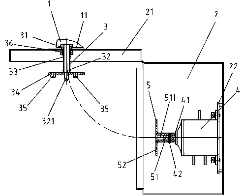
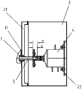
[0017] This example figure 1 , figure 2 As shown, it includes an operating handle 1 arranged outside the door panel 21 of the power distribution cabinet, a clutch mechanism 3 arranged in the power distribution cabinet 2 and connected to the operating handle 1, and a turntable 5 connected to the combined switch 4 fixed in the power distribution cabinet. The combined switch 4 is fixed on the box wall of the distribution cabinet 2 through the fixing plate 22, and the switch nameplate 11 for indicating the working state of the switch is provided on the door panel 21 of the distribution cabinet at the lower side of the operating handle 1.

[0018] The clutch mechanism 3 includes a guide sleeve 31, a guide rod 32, a compression spring 33, a shift fork plate 34, and a pair of positioning pins 35. The guide sleeve 31 is fixed on the door panel 21 of the power distribution cab...


PUM


Abstract

The invention discloses an operating clutch device of a power distribution cabinet combined switch, which comprises an operating handle, a clutch mechanism, and a turntable connected with a combined switch. The clutch mechanism comprises a guide sleeve, a guide rod, a compression spring, a shifting fork disc and a pair of positioning pins, wherein the guide sleeve is fixed on the door panel of a power distribution cabinet through a fixing nut, the guide rod penetrates through the guide sleeve, one end of the guide rod is fixedly connected with the operating handle and the other end of the guide rod is fixedly connected with the shifting fork disc; and the pair of positioning pins is respectively fixed on the shifting fork disc, the compression spring is movably sheathed on the guide rod, a shaft sleeve on one side of the turntable is fixedly connected with the rotating shaft of the combined switch, the inner hole of the shaft sleeve is matched with the other end of the guide rod and a pair of positioning pin holes which are matched with the heads of the pair of positioning pins are arranged on the surface of the turntable. The operating clutch device of the power distribution cabinet combined switch has a compact structure, is simple to operate and is reliable to work. When circular motion for opening and closing is carried out under the situation that the repeatability precision and the rigidness of the door panel of the power distribution cabinet are poor, the operating clutch device can be engaged and disengaged easily.

Description

technical field [0001] The invention relates to a switch control device, in particular to a combined switch control device for a power distribution cabinet, which belongs to the technical field of power transmission and distribution. Background technique [0002] Combination switches, especially marine electrical combination switches, are small in size, simple in structure, and reliable in action. They are widely used in ship power distribution systems, such as switchboards, charging and discharging boards, etc.; they are often used as isolating switches in switchboards. The discharge board is used as a charging and floating charging selection switch; its shape is different, and its capacity varies greatly, from a few amperes to hundreds of amperes or even larger; but the common feature is: the manual rotation handle drives the switch shaft to rotate, thereby controlling The switch is turned on and off, and the switch shaft is perpendicular to each terminal of the switch; wh...

Claims


Application Information

Patent Timeline
Patent Type & Authority Patents(China)
IPC IPC(8): H02B13/00
Inventor 冯学东凌有临
Owner 镇江四洋柴油机制造有限公司
Why Eureka
Try Eureka