Image reading apparatus and multi-function machine

An image reading device and clutch technology, applied in the directions of image communication, electrical components, etc., can solve the problems of limited irradiation area, reduced image data quality, and high manufacturing cost of the image reading device, and achieve the effect of preventing damage and suppressing power consumption

Inactive Publication Date: 2007-10-10
SEIKO EPSON CORP
View PDF4 Cites 0 Cited by
  • Summary
  • Abstract
  • Description
  • Claims
  • Application Information

AI Technical Summary

Problems solved by technology

[0009] When using a fluorescent tube light source, there is a problem that it takes a long time from lighting up to stabilizing to a readable amount of light
In addition, when a light source using a fluorescent tube is used to ensure a wide irradiation area capable of irradiating the entire document, there is a problem that the size of the light source is increased, and the size of the image reading device accompanying the increase in the size of the light source is increased.
[0010] In addition, when using an LED light source, the original image can be read immediately after lighting, and compared with the case where a fluorescent tube is u

Method used


Image

  • Image reading apparatus and multi-function machine
  • Image reading apparatus and multi-function machine
  • Image reading apparatus and multi-function machine

Examples


no. 1 approach

[0057] A preferred first embodiment of the image reading device of the present invention will be described in detail below with reference to the drawings. This first embodiment shows an example of a scanning device suitable for realizing the image reading device of the present invention.

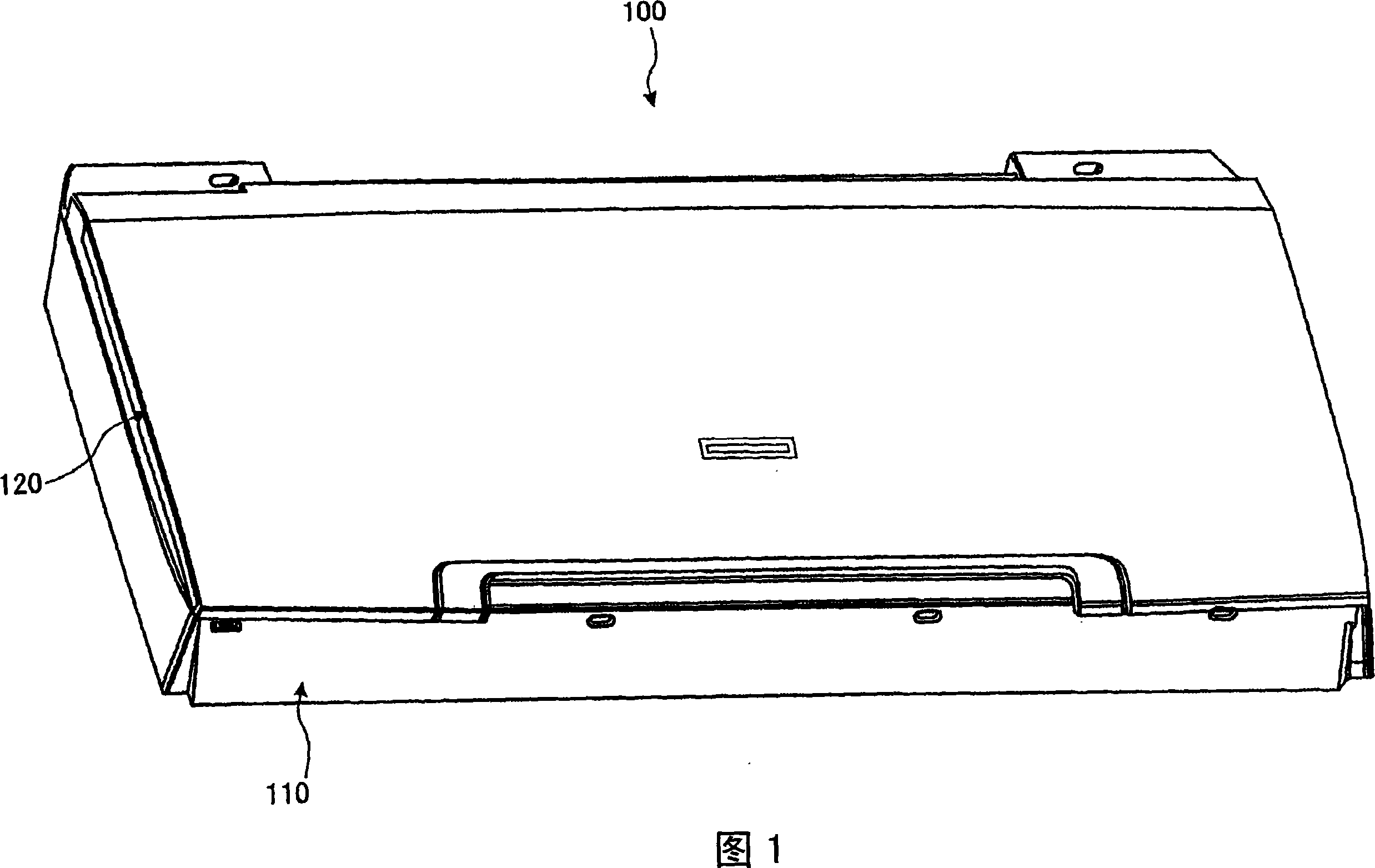
[0058] FIG. 1 is a perspective view showing the appearance of a scanning device according to a first embodiment. First, the appearance of the scanning device according to the first embodiment will be described using FIG. 1 . As shown in FIG. 1 , the scanning device 100 has a main body unit 110 and a transmission type document light source unit (hereinafter referred to as “TPU unit”) 120 .

[0059] The TPU unit 120 is disposed opposite to the main body unit 110, and is connected to the main body unit 110 through a hinge portion (see FIG. 3 ). The TPU unit 120 is connected to the main body unit 110 so as to be rotatable in a direction away from the main body unit 110 from the state shown in ...

no. 2 approach

[0111] A second preferred embodiment of the image reading device of the present invention will be described in detail below with reference to the drawings. This second embodiment shows an example of a scanning device suitable for realizing the image reading device of the present invention. In the second embodiment, the same parts as those in the first embodiment are denoted by the same symbols, and description thereof will be omitted.

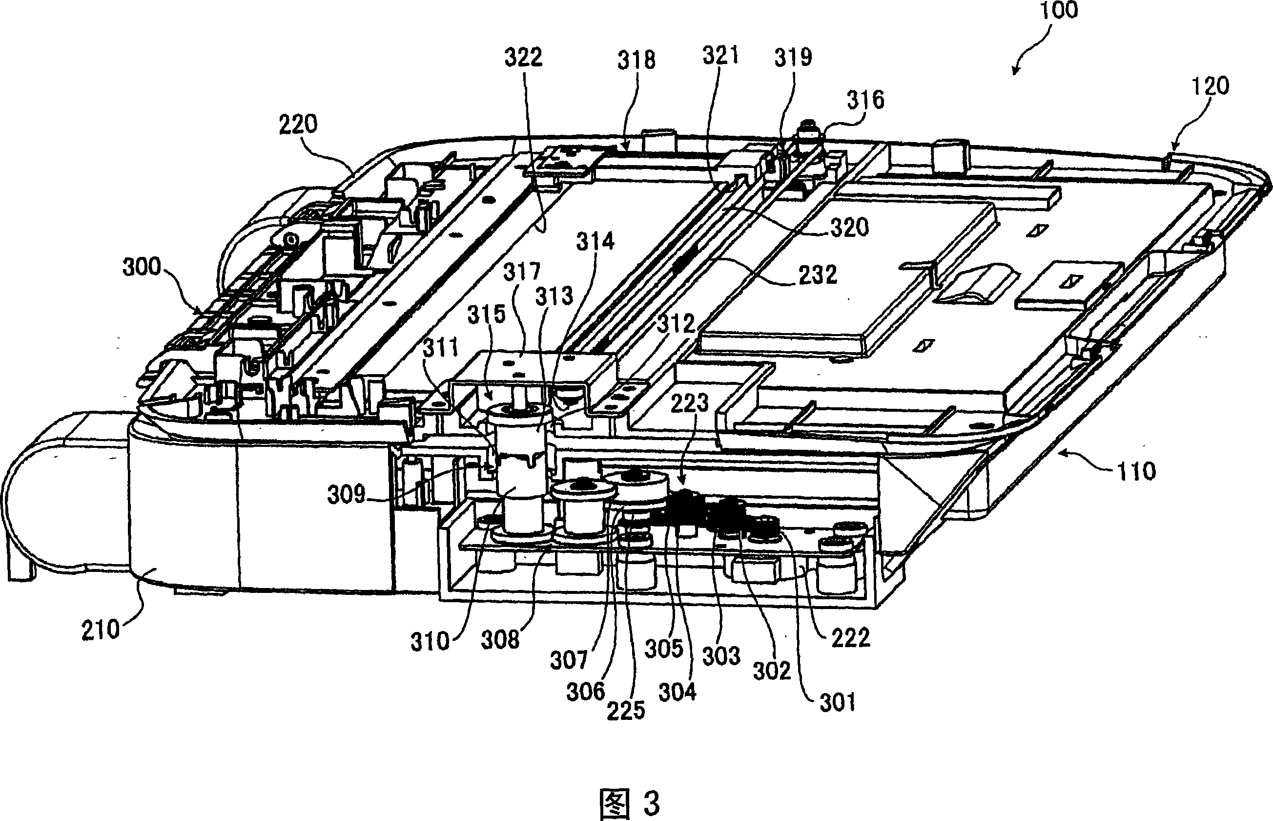
[0112] FIG. 7 is a perspective view showing a partially cutaway scanning device 100 according to the second embodiment. In FIG. 7 , a state where the upper TPU case of the TPU case 230 is taken out and a part of the main body case 210 is cut off is shown. Next, each part that transmits the driving force of the motor 222 will be described with reference to FIG. 7 .

[0113] As shown in FIG. 7 , on the transmission wheel 307 , a magnetic body 710 constituting a part of the connection mechanism 709 is connected through a plurality of transmissio...

no. 3 approach

[0128] A preferred third embodiment of the image reading device of the present invention will be described in detail below with reference to the drawings. This third embodiment shows an example of a multifunction peripheral suitable for realizing the image reading device and the multifunction peripheral of the present invention. In the third embodiment, the same parts as those in the above-mentioned first and second embodiments are denoted by the same symbols, and description thereof will be omitted.

[0129] 10 is a perspective view showing the appearance of a multifunction peripheral according to a third embodiment. A multifunction peripheral 1000 according to the third embodiment includes: the scanner device 100 described in the above-mentioned first and second embodiments; and a printer 1001 as an image forming device that forms an image on a recording medium corresponding to The intensity of light in the imaging element 217 included in the scanning device 100 .

[0130]...


PUM


Abstract

An image reading apparatus has a light source and an image capturing device disposed to face each other with a document table interposed therebetween. The image reading apparatus includes: an image capturing device moving mechanism, operable to perform a moving operation for moving the image capturing device in a scanning direction; and a light source moving mechanism, operable to move the light source in the first direction with the movement operation performed by the image capturing device moving mechanism.

Description

[0001] References to related applications [0002] The entire disclosures of Japanese Patent Applications Nos. 2006-102957, 2006-102958, and 2006-102959 filed on April 4, 2006 are expressly incorporated herein by reference. technical field [0003] The present invention relates to an image reading device and a multifunction peripheral. Background technique [0004] In the prior art, there is such an image reading device, in addition to illuminating the original plate holding the original from the same side as the imaging element, and detecting the intensity of light reflected by the original to optically read the reflection type reading mechanism of the image of the original. , there is also an image reading device in which a reflective plate reflecting light irradiated from the light source is provided on the opposite side of the light source with respect to the original, whereby reflection-type and transmissive-type original images are read by the same reading mechanism. ...

Claims


Application Information

Patent Timeline
IPC IPC(8): H04N1/04H04N1/028H04N1/024H04N1/10
Inventor 小口智
Owner SEIKO EPSON CORP
Why Eureka
Try Eureka