

Electronic device and charging method thereof
The technology of an electronic device and charging method is applied in the direction of circuit device, battery circuit device, secondary battery charging/discharging, etc., and can solve the problems of electronic devices that cannot be charged, voltage backflow, etc.
- Summary
- Abstract
- Description
- Claims
- Application Information
AI Technical Summary
Problems solved by technology
Method used
Image

Examples
no. 1 example
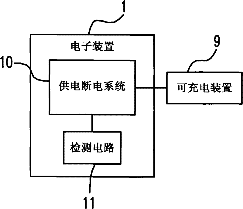
[0022] Please refer to figure 1 , which is a schematic diagram of component connections of the electronic device according to the first embodiment of the present invention. In this embodiment, the electronic device 1 can be used to charge a rechargeable device 9 . The electronic device 1 may include a power supply interruption system 10 and a detection circuit 11 . When the detection circuit 11 detects that the rechargeable device 9 has been fully charged, the power supply interruption system 10 will cut off the charging operation of the rechargeable device 9 . The design of this embodiment can prevent the voltage or current that has been charged in the rechargeable device 9 from gradually flowing back into the power supply and interruption system 10 after a period of time. This kind of situation often occurs when the electronic device 1 itself has the function of automatically switching between the normal mode and the power saving mode to comply with environmental protectio...
no. 2 example
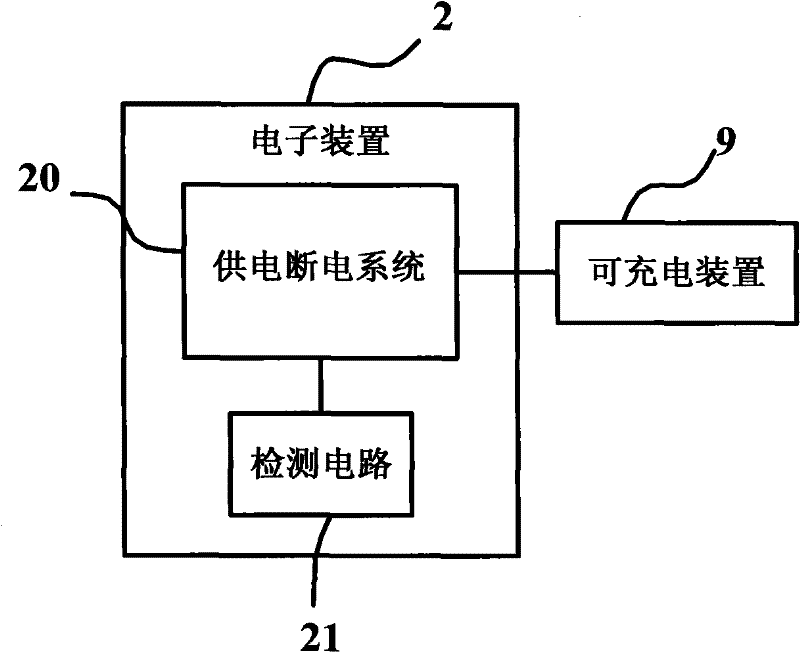
[0025] Please refer to figure 2 , the component connection relationship of the electronic device in this embodiment can be as follows figure 2 shown. In this embodiment, the electronic device 2 can be used to charge a rechargeable device 9 . The electronic device 2 may include a power supply interruption system 20 and a detection circuit 21 . When the detection circuit 21 detects that the rechargeable device 9 has not been fully charged and the power supply interruption system 20 is in a shutdown state, the detection circuit 21 controls the power supply interruption system 20 to continue supplying power to the rechargeable device 9 . When a traditional electronic device is turned off, only a small amount of standby power is consumed, and it cannot be charged externally. Often, the charging cannot be continued before the charging is completed, or even half-charged, which causes considerable troubles for users. The design of this embodiment, using the detection circuit 21 f...
no. 3 example
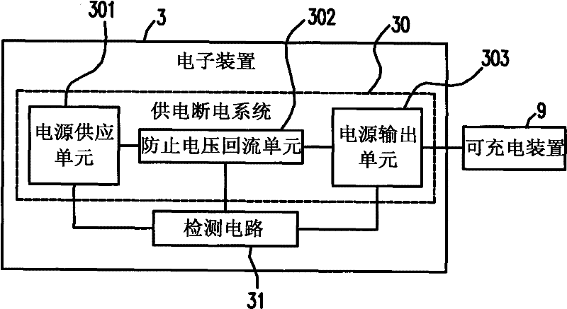
[0028] Please refer to image 3 , the component connection relationship of the electronic device in this embodiment can be as follows image 3 shown. In this embodiment, the electronic device 3 can be used to charge a rechargeable device 9 . The electronic device 3 may include a power supply interruption system 30 and a detection circuit 31, and the power supply interruption system 30 may include a power supply unit 301, a voltage backflow prevention unit 302 and a power output unit 303, and the connection relationship is as follows: image 3 As shown; wherein, the power supply unit 301 outputs current to charge the rechargeable device 9 through the voltage backflow prevention unit 302 and the power output unit 303 .
[0029] When the detection circuit 31 detects that the rechargeable device 9 has been fully charged, the detection circuit 31 will send a signal to control the voltage backflow prevention unit 302 so that the power supply unit 301 and the power output unit 303 ...
PUM
 Abstract
Description
Claims
Application Information