Prestressed anti-fatigue steel beams

A prestressed steel strand and prestressed technology, applied in the direction of joists, girders, truss beams, etc., can solve the problems of major accidents, sudden accidents, low material strength utilization, etc., and achieve the effect of improving fatigue resistance

Inactive Publication Date: 2011-12-28
马人乐
View PDF10 Cites 18 Cited by
  • Summary
  • Abstract
  • Description
  • Claims
  • Application Information

AI Technical Summary

Problems solved by technology

The higher the material strength, the worse the connection category, and the more repetitions of fatigue loads, the lower the material strengt

Method used


Image

  • Prestressed anti-fatigue steel beams
  • Prestressed anti-fatigue steel beams
  • Prestressed anti-fatigue steel beams

Examples


Embodiment 1

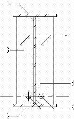
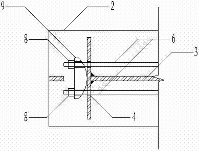
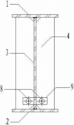
[0024] Embodiment 1: as Figure 1-Figure 6 As shown, the device consists of upper flange 1, lower flange 2, web 3, support stiffening plate and prestressed anchor plate 4, anchor hole 5, high-strength prestressed steel strand 6, anchor stiffening plate 7, anchor Head 8, curved plate 9, support steel corbel 10 and anti-sideshift pad 11 are formed. The upper flange 1, the lower flange 2 and the web 3 form a welded H-shaped steel beam. Both ends of the H-shaped steel beam are fixed on the support steel corbel 10, and anchor plates 4 are welded on both sides of the web 3 above the support steel corbel 10. The anchor plate 4 is used both as a steel beam support stiffening plate and also as a prestressed anchor plate. One end (right end) of the H-shaped steel beam is provided with anchor holes 5 on both sides symmetrical to the web 3 at the anchor plate 4 near the lower flange, and anchor holes 5 are welded with anchorage area stiffeners 7 up and down. Beam other end (left end) i...

Embodiment 2

[0026] Embodiment 2: The device described in Embodiment 1 is used for the box-shaped steel girder of the bridge crane, and the prestressed steel strands 6 are arranged on both sides of the web 3 near the tension flange of the box-shaped steel beam of the bridge crane, and the It applies a pretension. Similarly, after deducting the loss of prestress, the pretension produces compressive stress on the tension flange. The steel beam is not stretched under fatigue, and the fatigue resistance is satisfactory. Due to the use of high-strength materials and improved material utilization, the weight of the box girder can be greatly reduced, which is beneficial to the reduction of long-term energy consumption of the bridge crane.


PUM


Abstract

The invention belongs to the technical field of civil engineering, and specifically relates to a prestressing anti-fatigue girder. The prestressing anti-fatigue girder comprises a top flange, a bottom flange, a web, a bearer stiffening plate and prestressing anchor slab, anchor holes, a high-strength prestressing steel strand, an anchoring stiffening plate, an anchor head, an arc plate, a bearer steel bracket and lateral movement proof cushion block. The prestressing steel strand is penetrated into anchor holes which are near to a tensile flange and are symmetrical on two sides of the web, and is anchored by the anchor head after stretch-draw, so as to generate a precompression on a girder tensile area. After prestressing relaxation, the prestressing steel strand has a pressure stress larger than amplitude of a self-weight stress and a fatigue tensile stress; and the girder bottom flange will not be subjected to tension under compound effects of deadweight and fatigue load. Therefore,a fatigue problem id solved. According to the invention, a design fatigue stress amplitude of the bottom flange is increased from a former one limited in an allowed fatigue stress amplitude to one approaching a design strength f, so as o substantially increase anti-fatigue capability and change a fatigue brittle failure to a ductility strength problem. An ultimate strength of the bottom flange isincreased by one time, so as to substantially increase material utilization rate of high-strength steel.

Description

technical field [0001] The invention belongs to the technical field of civil engineering, and in particular relates to a prestressed anti-fatigue steel beam. Background technique [0002] At present, the allowable fatigue stress amplitude of anti-fatigue steel beams (such as heavy-duty crane girders, driving main girders, bridges, etc.) is low, and high-strength steel has no advantage in fatigue resistance. The ratio of allowable fatigue stress amplitude to strength Much lower than the ratio of fatigue effects and strength effects. For the main anti-fatigue steel beams, except for Q235 steel and type 2 connections, which can simultaneously exert material strength and fatigue resistance, the materials in other cases are controlled by anti-fatigue, and the utilization rate of material strength is insufficient. The higher the material strength, the worse the connection category, and the higher the number of fatigue load repetitions, the lower the material strength utilization....

Claims


Application Information

Patent Timeline
IPC IPC(8): E04C3/10
Inventor 马人乐
Owner 马人乐
Why Eureka
Try Eureka