Small centrifugal water pump with impeller directly driven by internal rotor motor

An electric motor and centrifugal technology, applied in the direction of non-variable pumps, machines/engines, liquid fuel engines, etc., can solve the problems of complicated conduit connection structure, processing and installation, loose joints, and prone to water leakage

Active Publication Date: 2013-04-24
HANYU GRP CO LTD
View PDF13 Cites 1 Cited by
  • Summary
  • Abstract
  • Description
  • Claims
  • Application Information

AI Technical Summary

Problems solved by technology

[0003] 1. The connection structure and processing and installation of the conduit are relatively complicated;
[0004] 2. Due to aging and loose joints in the conduit, water leakage is prone to occur, which reduces the reliability of operation

Method used


Image

  • Small centrifugal water pump with impeller directly driven by internal rotor motor
  • Small centrifugal water pump with impeller directly driven by internal rotor motor
  • Small centrifugal water pump with impeller directly driven by internal rotor motor

Examples


Embodiment Construction

[0028] The embodiments of the present invention are mainly improvements to the applicant's prior art products. Relevant designs of these prior art products can be found in the applicant's prior utility model patent specifications CN 200420047013, CN 200620054699 and CN 200720148584. For the relevant content of the prior art that needs to be applied in the embodiment of the present invention, which is not described in this application document, the above specification can be referred to.

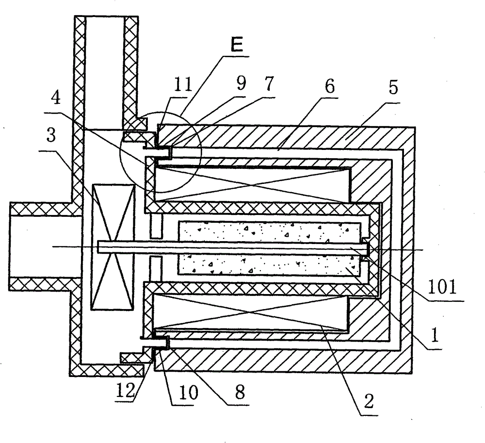
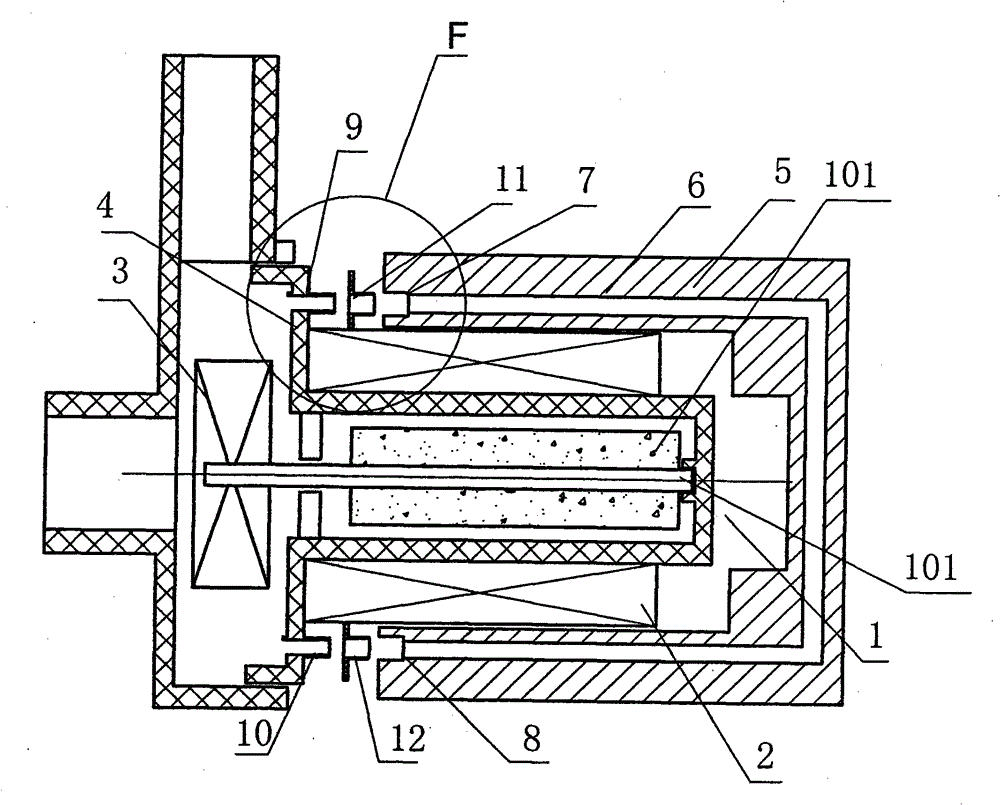
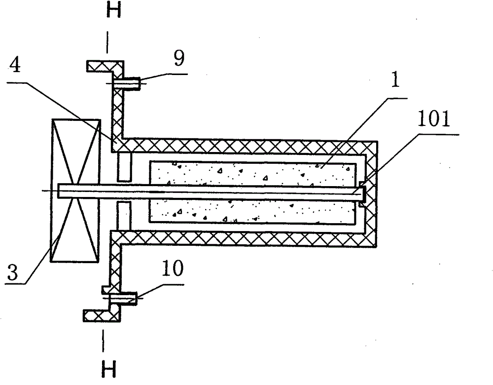
[0029] The structure of the small centrifugal water pump in the first embodiment of the present invention is as follows: figure 1 , figure 2 , image 3 , Figure 5 , Image 6 , Figure 7 , Figure 11 with Figure 12 As shown, it is mainly composed of three parts: motor, pump structure and water cooling structure.

[0030] Motors include:

[0031] - permanent magnet rotor 1;

[0032] - the stator core 2, the inner hole of which surrounds the rotor 1, and its shape is roughly cuboid;...


PUM


Abstract

The invention relates to a small centrifugal water pump with an impeller directly driven by an internal rotor motor, comprising the motor and a pump structure, wherein the motor comprises a rotor, a stator core surrounding the rotor and a winding installed on the stator core; the pump structure comprises the impeller rotatably coupled with the rotor on the same axis and a scroll surrounding the impeller and also comprises a metal body which is in tight contact with the stator core and is provided with an inner cavity; the end face at the side of the metal body, facing the scroll, is vertical to the axis and is provided with at least 2 interfaces penetrating through the inner cavity; the end face at the side of the scroll, facing the motor, is vertical to the axis and is provided with openings penetrating through the inner cavity of the scroll; the number of the openings is same as that of the interfaces; the end face at the side of the metal body, facing the scroll, is in butt joint with the end face at the side of the scroll, facing the motor; and the interfaces and the openings are connected one to one. Due to the design, conduit connection in the traditional technology is eliminated, the complexity of the structure and processing and mounting is reduced, the problem of water leakage caused by conduit ageing and joint loosening can be eliminated, and the reliability is improved.

Description

technical field [0001] The invention relates to a centrifugal water pump, in particular to a small centrifugal water pump in which an inner rotor motor directly drives an impeller. In the International Patent Classification Table, the classification may belong to F04D29 / 58. Background technique [0002] In order to reduce the temperature rise of the motor driving the water pump, Chinese utility model patents ZL90207417.2, ZL00253552.1 and ZL200420114447.3 propose a technical solution for cooling the water flow output by the water pump that the motor is equipped with a water-cooled radiator to feed into its transmission. The specific method is to lead the water flow with sufficient pressure difference from the output (high pressure) and input (low pressure) ends of the water pump to the water cooling radiator located in the motor casing. Since the output (high pressure) and input (low pressure) of the water pump are usually far away from the water-cooled radiator, it is neces...

Claims


Application Information

Patent Timeline
Patent Type & Authority Patents(China)
IPC IPC(8): F04D13/06F04D29/42
Inventor 马余洋池文茂卓春光
Owner HANYU GRP CO LTD
Why Eureka
Try Eureka