
Lighting device with microstructured brightness enhancing film

A lighting device and brightness enhancement film technology, which is applied in the direction of lighting devices, lighting device components, lighting and heating equipment, etc., can solve the problems of reducing manufacturing costs, increasing manufacturing costs, and low central luminous intensity, so as to reduce manufacturing costs , Improve luminous efficiency, good practical effect

Inactive Publication Date: 2011-12-28
AUTOMOTIVE RES & TESTING CENT
View PDF5 Cites 3 Cited by
  • Summary
  • Abstract
  • Description
  • Claims
  • Application Information

AI Technical Summary

Problems solved by technology

[0004] In order to solve the shortcomings and limitations of the prior art lighting device using a planar light source related to poor luminous efficiency, low central luminous intensity and increased manufacturing cost, the purpose of the present invention is to provide a lighting device with a microstructure brightness enhancing film , which is equipped with a microstructure brightness enhancement film, the zigzag Fresnel light concentrating part of the microstructure brightness enhancement film changes periodically more than twice, and cooperates with the setting of the reflector, which can effectively focus the light and improve the luminescence Efficiency, increase the central luminous intensity and reduce the number of OLEDs used for planar light sources, thereby reducing manufacturing costs and excellent practicability

Method used


Image

  • Lighting device with microstructured brightness enhancing film
  • Lighting device with microstructured brightness enhancing film
  • Lighting device with microstructured brightness enhancing film

Examples


Embodiment Construction

[0026] The technical solutions adopted by the present invention to achieve the intended invention purpose are further described below in conjunction with the accompanying drawings and preferred embodiments of the present invention.

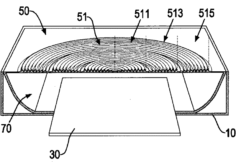
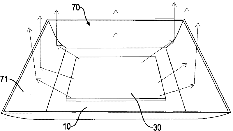
[0027] A first preferred embodiment of a lighting device with a microstructure brightness enhancing film provided by the present invention, such as figure 1 As shown, it includes: a casing 10, a planar light source 30, a microstructure brightness enhancement film 50, a reflector 70 and other components, wherein:

[0028] Such as figure 1 As shown, the housing 10 is hollow, and the housing 10 is a component of the prior art, and is not the focus of the present invention, and its detailed structure will not be repeated.

[0029] Such as figure 1 , 2 As shown, the planar light source 30 is horizontally fixed in the casing 10 and has a top surface. Preferably, the planar light source 30 is formed by a plurality of organic light emitting diodes arra...


PUM


Abstract

The invention relates to a lighting device with a microstructure brightness enhancement film, which includes a housing, a plane light source, a microstructure brightness enhancement film and a reflector. The microstructure brightness enhancement film is fixed on the housing and located above the plane light source. The brightness enhancement film is a light-transmitting thin sheet with a top surface, a bottom surface and a Fresnel light-concentrating part. The cross-sectional shape in the vertical direction is zigzag and changes periodically from the center to the outer periphery more than twice; in this way, the light can be effectively focused, the luminous efficiency can be improved, the luminous intensity of the center can be increased, and the loss of the plane light source can be reduced. The number of OLEDs is used, thereby reducing the manufacturing cost, and the practicability is excellent.

Description

technical field [0001] The invention relates to an appliance capable of illuminating, in particular to an illuminating device with a microstructure brightness-enhancing film. Background technique [0002] At present, generally existing planar light sources project a field shape of the light source as Lambertian, that is, a Lambertian light source. The divergence angle of the light emitted by the planar light source is large, which is likely to cause the disadvantages of poor luminous efficiency and low central luminous intensity. When it is applied to lighting devices, such as taillights, it is necessary to use multiple OLED [Organic Light-Emitting Diode organic light-emitting Diodes] to meet the regulatory requirements for lighting brightness, which will greatly increase the manufacturing cost. [0003] Therefore, the prior art illuminating device using a planar light source has the disadvantages of poor luminous efficiency, low central luminous intensity, and increased ma...

Claims


Application Information

Patent Timeline
Patent Type & Authority Applications(China)
IPC IPC(8): F21S2/00F21V5/00F21V7/00F21V17/00
CPCY02B20/36Y02B20/30
Inventor 何耀民许日滔江志彬
Owner AUTOMOTIVE RES & TESTING CENT
Learn More