Laser-micro-engraving process and laser-micro-engraving machine

A laser engraving and laser machine technology, applied in decorative arts, processing models, etc., can solve problems such as missing graphics, reduce contact probability and improve safety.

Active Publication Date: 2018-10-23
深圳市太阳鸟展示包装有限公司
View PDF9 Cites 0 Cited by
  • Summary
  • Abstract
  • Description
  • Claims
  • Application Information

AI Technical Summary

Problems solved by technology

[0004] However, at the engraving site, the staff all carry mobile phones and often answer the phone, and the signal of the mobile phone will interfere with the fluctuation of the light proj

Method used


Image

  • Laser-micro-engraving process and laser-micro-engraving machine
  • Laser-micro-engraving process and laser-micro-engraving machine
  • Laser-micro-engraving process and laser-micro-engraving machine

Examples


Embodiment 1

[0052] Embodiment 1, a laser engraving process, the steps are as follows:

[0053] The first step is to turn on the internal engraving machine, edit the pattern and text to be engraved, operate the counting software according to the pattern and text of the product, and then set the number of processing layers to 3 layers and the processing distance to 0.86;

[0054] If the number of processing layers is set below 3 layers, the fineness of the pattern will not be high, and the pattern density will be insufficient, which will make the continuity of the pattern lines poor; if the number of processing layers is higher than 3 layers, the processed pattern will be blurred.

[0055] If the processing distance is lower than 0.86, the fineness will not be high, and the pattern density will not be enough, which will make the continuity of the pattern lines poor; if the processing distance is higher than 0.86, the inner carving will rot.

[0056] The second step is to wipe the object to ...

Embodiment 2

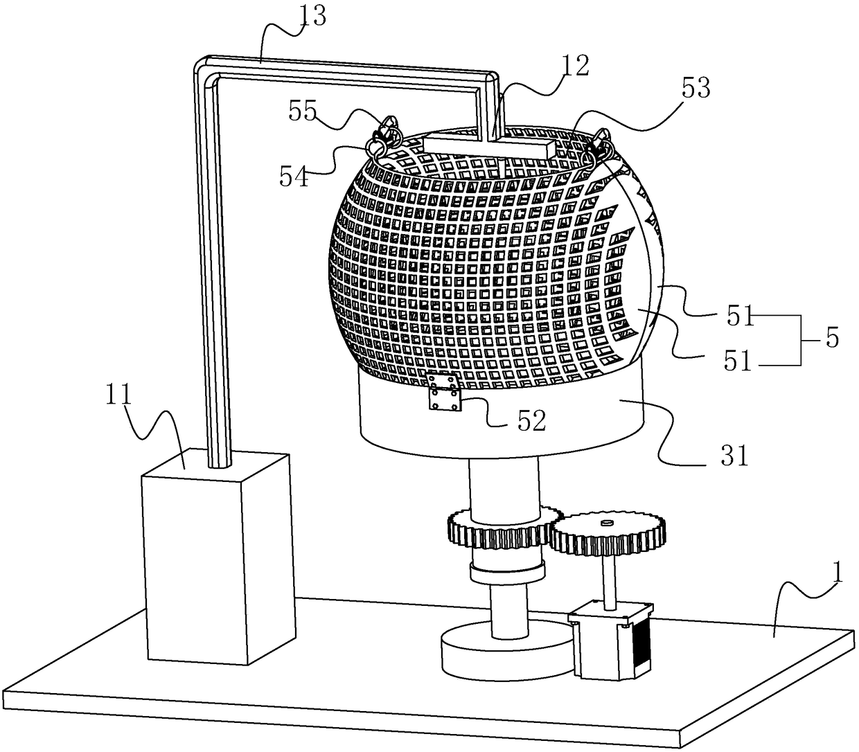
[0062] Embodiment 2, laser engraving machine, such as figure 1 As shown, it includes a machine base 1, which is a flat metal plate on which a laser machine 11 is fixed, and the laser machine 11 is provided with a laser head 12 for projecting laser light.

[0063] The laser machine 11 and the laser head 12 are connected by a connecting rod 13; the laser head 12 is on the upper end of the connecting rod 13, and the laser head 12 projects the laser line downward. The laser head 12 can be rotated by computer control to form the required laser line;

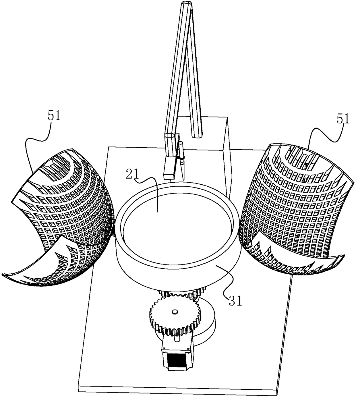
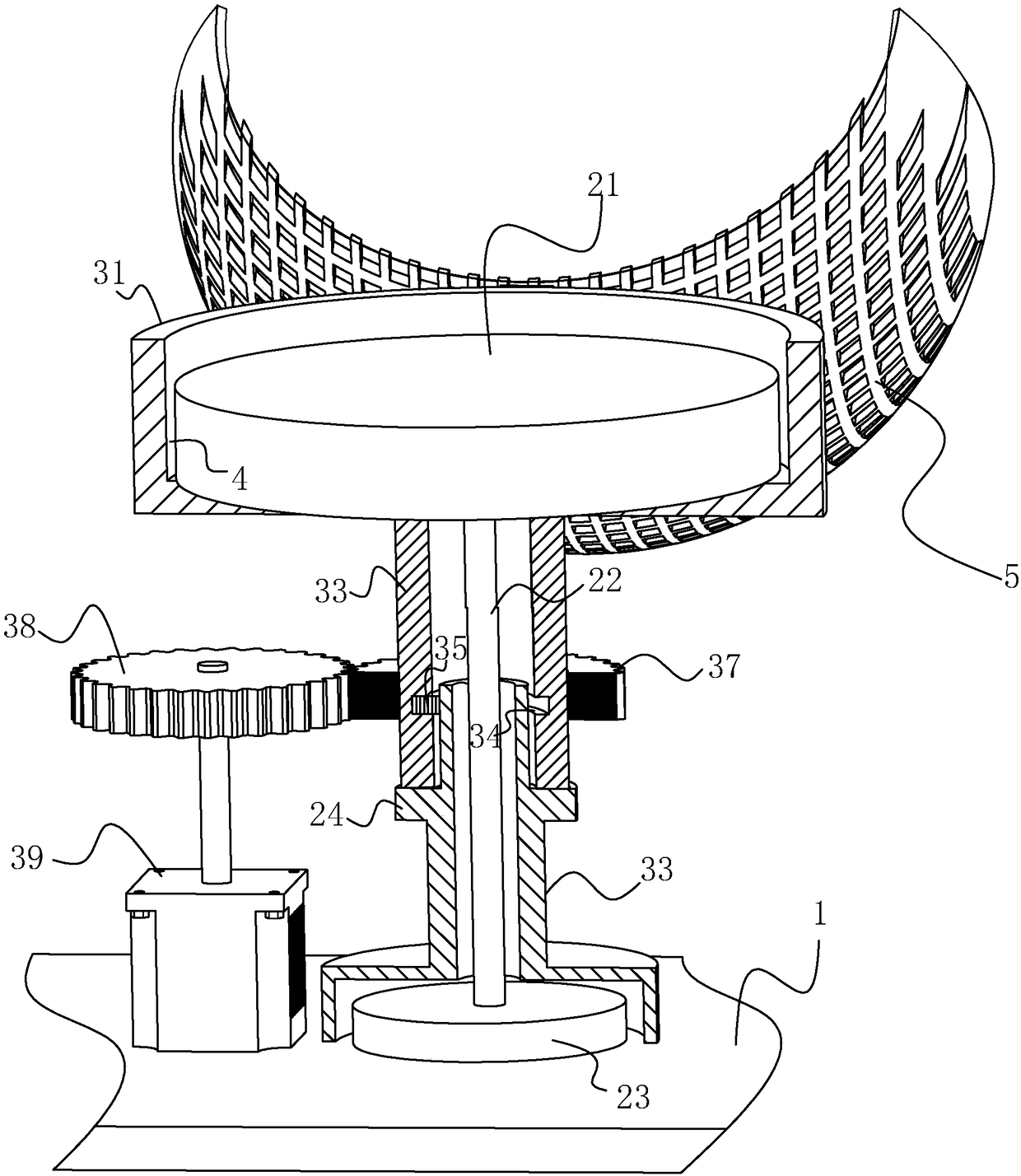
[0064] A metal mesh cover 5 is installed on the upper surface of the machine base 1, and the metal mesh cover 5 includes two hemispherical metal mesh sheets 51, and the two metal mesh sheets 51 are rotatably connected to both sides of the swivel 31 through hinges 52;

[0065] The metal mesh sheets 51 are folded together to form a spherical shape. At this time, the lower edges of the metal mesh sheets 51 collide with the swivel 31, an...


PUM


Abstract

The invention discloses a laser-micro-engraving process and a laser-micro-engraving machine to overcome the problem of partial missing of engraved patterns caused by cell phone signals. According to atechnical scheme in the invention, the laser-micro-engraving process comprises the following steps: step 1, starting the laser-micro-engraving machine, subjecting a pattern and characters to be engraved to editing, and in virtue of point cloud calculating software, setting corresponding parameters according to a product and requirements and carrying out point cloud calculation on the pattern andthe characters; step 2, placing a to-be-engraved object on a platform and allowing the laser head of the laser-micro-engraving machine to be aligned with the to-be-engraved object; step 3, placing a metal screen onto a platform, wherein the metal screen sleeves the laser head and the to-be-engraved object; and step 4, starting the laser head. The laser-micro-engraving machine comprises a machine seat; the platform is fixed on the machine seat and sleeved by a rotary ring; the machine seat is provided with a power source driving the rotary ring to rotate; the rotary ring is provided with the metal screen; and the metal screen is provided with a through hole allowing the laser head to be inserted, so negative influence of cell phone signals on laser-micro-engraving is reduced.

Description

technical field [0001] The invention relates to a laser engraving process and a laser engraving machine, more specifically, it relates to a laser internal engraving process and a laser internal engraving machine. Background technique [0002] In order for a laser to be able to engrave glass, its energy density must be greater than a certain critical value, or threshold, that destroys the glass. The energy density of a laser at a certain point is related to the size of its spot at that point. The smaller the spot of the same laser beam, the greater the energy density. In this way, through proper focusing, the energy density of the laser can be kept below the damage threshold of the glass before it enters the glass and reaches the processing area, and exceeds this critical value in the desired processing area. The laser generates pulses in a very short time, and its energy can heat and crack the crystal in an instant, resulting in tiny white spots that carve a predetermined ...

Claims


Application Information

Patent Timeline
IPC IPC(8): C03C23/00B44B1/00B44B1/06
CPCB44B1/006B44B1/06C03C23/0025
Inventor 刘家惠
Owner 深圳市太阳鸟展示包装有限公司
Why Eureka
Try Eureka