Flexible display device

A flexible display and device technology, applied in the direction of semiconductor devices, electric solid devices, organic semiconductor devices, etc., can solve the problems of easy cracking at the joints and interface cuts, damage to the organic electroluminescent device body, poor tolerance, etc. , to reduce the probability of moisture entering the encapsulation layer, improve the encapsulation effect, and increase the service life

Active Publication Date: 2017-11-17
BOE TECH GRP CO LTD
View PDF9 Cites 6 Cited by
  • Summary
  • Abstract
  • Description
  • Claims
  • Application Information

AI Technical Summary

Problems solved by technology

However, the devices in organic electroluminescent devices have poor tolerance to the surrounding environment. In the prior art, thin film packaging methods are used to isolate organic electroluminescent devices from the external environment, specifically, through the combination of multilayer organic-inorganic thin films encapsulation layer
[0003] When the organic electroluminescent device is packaged, the packaging layer is connected to the organic electroluminescent device. Since the bonding area between the packaging layer and the interface is unstable, when the edge of the organic electroluminescent device is cut, the packaging layer, interface The connection with the encapsulation layer and the cut of the interface are prone to cracks, allowing moisture to enter the encapsulation layer, causing damage to the organic electroluminescent device body and resulting in failure of the overall encapsulation

Method used


Image

  • Flexible display device
  • Flexible display device

Examples


Embodiment Construction

[0023] The following will clearly and completely describe the technical solutions in the embodiments of the present invention with reference to the accompanying drawings in the embodiments of the present invention. Obviously, the described embodiments are only some, not all, embodiments of the present invention. Based on the embodiments of the present invention, all other embodiments obtained by persons of ordinary skill in the art without making creative efforts belong to the protection scope of the present invention.

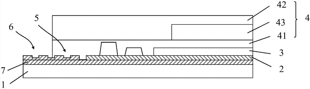
[0024] Please refer to Figure 1 to Figure 2 The flexible display device provided by the embodiment of the present invention includes: a base substrate 1, an insulating layer 2 disposed on the base substrate 1, an organic electroluminescent device body 3 disposed on the insulating layer 2, an organic electroluminescent device body 3 disposed on the organic electroluminescent On the light emitter body 3 is an encapsulation layer 4 that seals the organic electro...


PUM


Abstract

The invention relates to the technical field of display, and discloses a flexible display device. The flexible display device comprises a substrate, an insulating layer arranged on the substrate, an organic light emitting device body arranged on the insulating layer, and an encapsulation layer arranged on the organic light emitting device body and used for sealing the organic light emitting device body, wherein cutting grooves are formed in a packaged region in the connecting position between the insulating layer and the encapsulation layer. According to the flexible display device, by forming the cutting grooves in the packaged region in the connecting position between the insulating layer and the encapsulation layer, an effect of prolonging a path of water which enters the packaged region and then is in contact with the organic light emitting device body is achieved, thereby improving the encapsulation effect of the encapsulation layer, effectively lowering probability of water in entering the encapsulation layer, improving the body encapsulation success rate, also prolonging the service life of the organic light emitting device body, and further prolonging the service life of the flexible display device.

Description

technical field [0001] The invention relates to the field of display technology, in particular to a flexible display device. Background technique [0002] Organic electroluminescent devices have the characteristics of self-luminescence, high brightness, high contrast, low operating voltage, and flexible display, and are known as the most promising display devices. However, the devices in organic electroluminescent devices have poor tolerance to the surrounding environment. In the prior art, thin-film packaging methods are used to isolate organic electroluminescent devices from the external environment, specifically, through the combination of multilayer organic-inorganic thin films Form the encapsulation layer of the package. [0003] When the organic electroluminescent device is packaged, the packaging layer is connected to the organic electroluminescent device. Since the bonding area between the packaging layer and the interface is unstable, when the edge of the organic e...

Claims


Application Information

Patent Timeline
Patent Type & Authority Applications(China)
IPC IPC(8): H01L51/52H01L27/32
CPCH10K59/00H10K50/841H10K50/84H10K50/8426H10K50/844H10K71/851H10K59/12H10K59/124
Inventor 王有为张嵩宋平蔡鹏郭远征
Owner BOE TECH GRP CO LTD
Why Eureka
Try Eureka