MEMS microphone and forming method thereof

A technology of microphone and cavity, applied in the field of MEMS microphone and its formation, to achieve the effect of compact structure and avoiding noise

Active Publication Date: 2015-10-14
SEMICON MFG INT (SHANGHAI) CORP
View PDF8 Cites 7 Cited by
  • Summary
  • Abstract
  • Description
  • Claims
  • Application Information

AI Technical Summary

Problems solved by technology

[0006] The problem that the present invention solves is to reduce the noise of MEMS microphone

Method used


Image

  • MEMS microphone and forming method thereof
  • MEMS microphone and forming method thereof
  • MEMS microphone and forming method thereof

Examples


Embodiment Construction

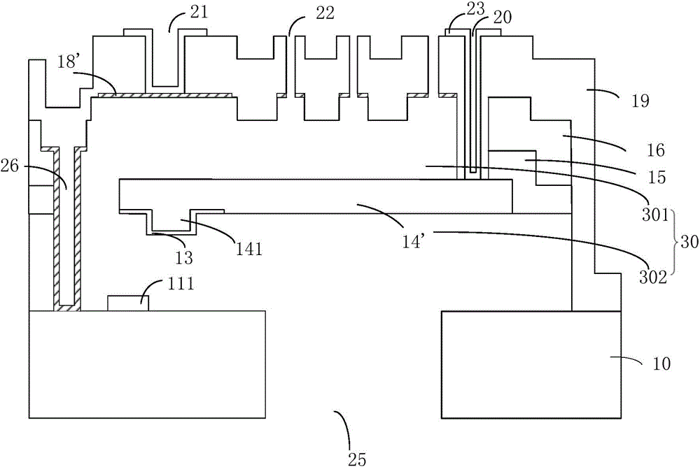
[0046] As described in the background art, existing MEMS microphones are noisy during use. In view of the above technical problems, the present invention provides a first protrusion on the single-arm beam as a movable sensitive film near the free end area to reduce the probability of the single-arm beam contacting other parts in the cavity. In addition, the first The protrusion is also covered with an insulating layer, so that even if the first protrusion contacts other components due to electrostatic adsorption, static charges will not be released through the movable sensitive film, thus avoiding the generation of noise in the MEMS microphone. The objectives, features, and advantages can be more obvious and understandable, and specific embodiments of the present invention will be described in detail below with reference to the accompanying drawings.

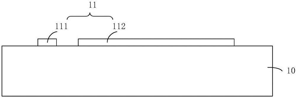
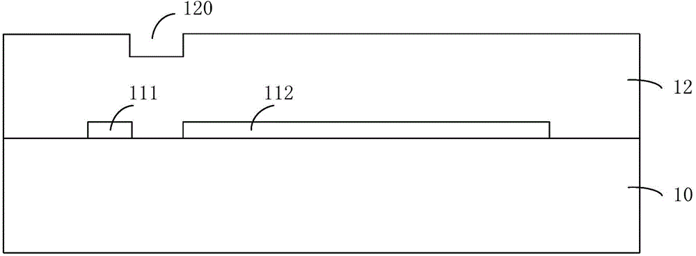
[0047] figure 1 Is a schematic structural diagram of a MEMS microphone provided by an embodiment of the present invention; Figur...


PUM


Abstract

The invention provides an MEMS microphone and a forming method thereof. According to the MEMS microphone, a first projection is arranged on a single-arm beam which is used as a movable sensitive film at a part that is next to a free end area, thereby reducing a possibility that the single-arm beam contacts with other components in a chamber. Furthermore an insulating layer covers the first projection so that static charges are not discharged through the movable sensitive film even after the first projection contacts with other components because of electrostatic attraction, thereby preventing a noise in the MEMS microphone.

Description

Technical field [0001] The invention relates to a microelectronic mechanical system technology, in particular to a MEMS microphone and a forming method thereof. Background technique [0002] Due to its miniaturization and thinness, MEMS microphones using microelectromechanical system technology have become one of the best candidates to replace electret condenser microphones (ECM) using organic membranes. [0003] MEMS microphones are miniature microphones made by etching pressure sensing diaphragms on semiconductors through the process of microelectronic mechanical systems. They are commonly used in mobile phones, earphones, notebook computers, cameras and automobiles. [0004] Existing MEMS microphones are prone to appear in the use process of the sensitive film as the movable electrode sticking to other components due to electrostatic adsorption during the vibration process, which causes static charges to conduct in the sensitive film and cause noise. [0005] In view of this, the p...

Claims


Application Information

Patent Timeline
Patent Type & Authority Applications(China)
IPC IPC(8): H04R19/04H04R31/00
Inventor 刘国安徐伟刘煊杰
Owner SEMICON MFG INT (SHANGHAI) CORP
Why Eureka
Try Eureka