Supercharge Your Innovation With Domain-Expert AI Agents!

A new type of combined switchgear and its installation and use method

A switchgear, combined technology, applied in switchgear, busbar/line layout, electrical components, etc., can solve the problem of inability to quickly replace faulty switchgear, achieve simple structure, improve replacement speed, and improve work efficiency.

Inactive Publication Date: 2011-12-28
XUJI GRP +1
View PDF5 Cites 3 Cited by
  • Summary
  • Abstract
  • Description
  • Claims
  • Application Information

AI Technical Summary

Problems solved by technology

However, this utility model patent cannot really quickly and conveniently carry out on-site installation and debugging of switch cabinets, nor can it realize rapid replacement of faulty switch cabinets

Method used


Image

  • A new type of combined switchgear and its installation and use method
  • A new type of combined switchgear and its installation and use method
  • A new type of combined switchgear and its installation and use method

Examples


Embodiment Construction

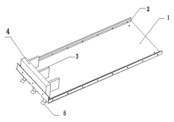
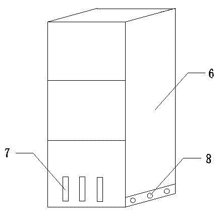
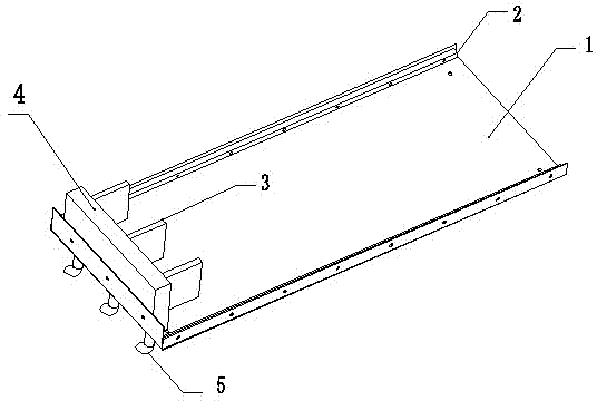
[0020] Such as figure 1 with figure 2 As shown, the present invention includes a switch cabinet body 6 capable of performing conventional power transmission and distribution functions, and a base board 1 provided with a contact base 4, and the contact base 4 is provided with a contact row 3 and a cable connection hole. The foundation plate 1 can be constructed together with the civil engineering, or be fixed at the required installation position by bolts. During installation, pass the outgoing cable 5 through the cable connection hole to connect to the contact row 3, and then fix the outgoing cable 5 with bolts to ensure that the outgoing cable 5 does not fall off or loose during the work. At this time, the installation of the foundation board 1 is completed. It is also possible not to provide a cable connection hole, but directly connect the outlet cable 5 to the terminal of the contact row 3. The switch cabinet body 6 is provided with a contact row socket 7 that is matched ...


PUM


Abstract

The invention discloses a new type combined switchgear, which comprises a switchgear body and a base plate provided with a contact seat. The contact block is provided with a contact row for connecting outgoing cables, and the switchgear body is provided with a The contact row is matched with the contact row socket, and after the contact row is inserted into the contact row socket, it is electrically connected with the internal circuit of the switch cabinet body. The present invention uses a base plate provided with contact rows and a switchgear body provided with contact row jacks. During the installation process, the cable is first connected to the contact row, and then the base board is realized by using the contact row and the contact row jacks. The connection with the switchgear body does not need to manually enter the switchgear for cable connection, and after the switchgear fails, only the switchgear body needs to be replaced, which improves the replacement speed, simple structure, greatly improves work efficiency, and reduces work difficulty .

Description

Technical field [0001] The invention relates to a complete set of switch equipment in the field of power equipment, in particular to a new type of combined switch cabinet and an installation and use method. Background technique [0002] During the on-site installation of the switchgear, due to the constraints of space, lifting equipment and other conditions, the on-site transfer of the switchgear is mainly carried by manual shoulders. In the process of combining the cabinets, a large number of simple tools such as crowbars are used to move the switchgear. Such operations can easily damage the main structure of the switch cabinet and bring hidden dangers to the safe operation of the equipment. During the commissioning and connection of the switchgear, the outgoing cables need workers to enter the narrow space in the switchgear for installation, which is not convenient for on-site construction, and once the switchgear fails, all connecting cables need to be removed, and the faulty ...

Claims


Application Information

Patent Timeline
IPC IPC(8): H02B1/20H02B3/00
Inventor 于世新贾伟王帮田黄晔矿孙鹏程
Owner XUJI GRP
Features
  • R&D
  • Intellectual Property
  • Life Sciences
  • Materials
  • Tech Scout
  • Unparalleled Data Quality
  • Higher Quality Content
  • 60% Fewer Hallucinations
Learn More