Scraping tool with blade lock assembly

a technology of scraper blade and assembly, which is applied in the field of scraper blade, can solve the problems of large inconvenience, severe opposite force of scraper blade b, and may be subject to severe force, and achieve the effect of fast replacement and assembly

Active Publication Date: 2013-01-22
LIN WEN CHEN
View PDF59 Cites 24 Cited by
  • Summary
  • Abstract
  • Description
  • Claims
  • Application Information

AI Technical Summary

Benefits of technology

[0008]The objective of the invention is to provide a scraping tool that can be assembled quickly and replaced for scraper blade. It is mainly composed of a jaw clamp that uses a fastener to attach to the back of a scraping section. The jaw clamp can swing back and forth with the fastener as pivot. On the scraping section there is a control button at the position that corresponds to the arm at the back end of the jaw clamp and the control button provides vertical push force against the arm at the back end of the jaw clamp. Therefore, it allows the front end of the jaw clamp works with the clamp of the scraping section to tighten the scraper blade and achieve the objectives of assembly stability and quick replacement for the scraper blade.
[0009]To achieve the above objectives, the scraping tool that can be assembled quickly and replaced for scraper blade mainly comprises an arm of suitable length extended from the back end of a jaw clamp toward the middle, a groove of equivalent shape to the jaw clamp at the back of the scraping section, fasteners by which the two sides of the jaw clamp are attached into the groove of the scraping section and as pivot to allow the jaw clamp to swing back and forth within the groove, a receptor at a position of the scraping section that corresponds forwardly to the arm at the back end of the jaw clamp and containing a long guide hole penetrating through the back groove to engage a long guide block inside to provide vertical sliding, a pillar at the bottom of the guide block, a control button which front side forms a release side with front edge and a pressure valve side with bottom edge, and wings at the back end for finger sliding and being able to rotate 90 degrees with a bolt as axle to connect to the top of the receptor in the front of the scraping section. When the control button operates 90-degree vertically in the long guide hole of the receptor, the release side in the front edge will correspond to the top of the long guide block and the guide block is free of pressure and able to move upward inside the guide hole. It also means the jaw clamp can swing inside the groove without holding the scraper blade. Thus, the scraper blade can freely move in or out of the clamp in the scraping section to achieve the objective of fast replacement. When the control button operates 90-degree horizontally, the pressure valve side at the bottom edge will correspond to the top of the long guide block and the guide block is under pressure without being able to move upward inside the guide hole. This also means the pillar at the bottom edge will push against the arm at the back end of the jaw clamp to generate a strong force for the front of the of the jaw clamp to grasp the scraper blade and achieve the objective of assembly stability for scraper blade.

Problems solved by technology

First, when the scraper blade 16 is assembled inside the clamp 14 of the scraping section 11, it uses the pressing and tightening force provided by the screws 17 running between the jaw clamp 15 and the scraping section 11. To achieve the tightening, there will be at least three screws 17. In other words, it is necessary to repeatedly loosen and tighten three screws 17 to replace the scraper blade 16. This causes a great deal of inconvenience.
Second, the jaw clamp 15 uses screws 17 to apply tightening force on the scraper blade 16. But the scraper blade 16 deviates the screw 17 tightening force and is located on one side. When the screws are not appropriately tightened, the scraper blade 16 may be subject to severe opposite force when it is used for high-impact scraping. If the scraper blade 16 is not assembled properly, there is always a risk of jumping out of the clamp 14 of the scraping section 11.

Method used


Image

  • Scraping tool with blade lock assembly
  • Scraping tool with blade lock assembly
  • Scraping tool with blade lock assembly

Examples


Embodiment Construction

[0017]The following uses figures with a preferred embodiment to explain the characteristics and function for the invention:

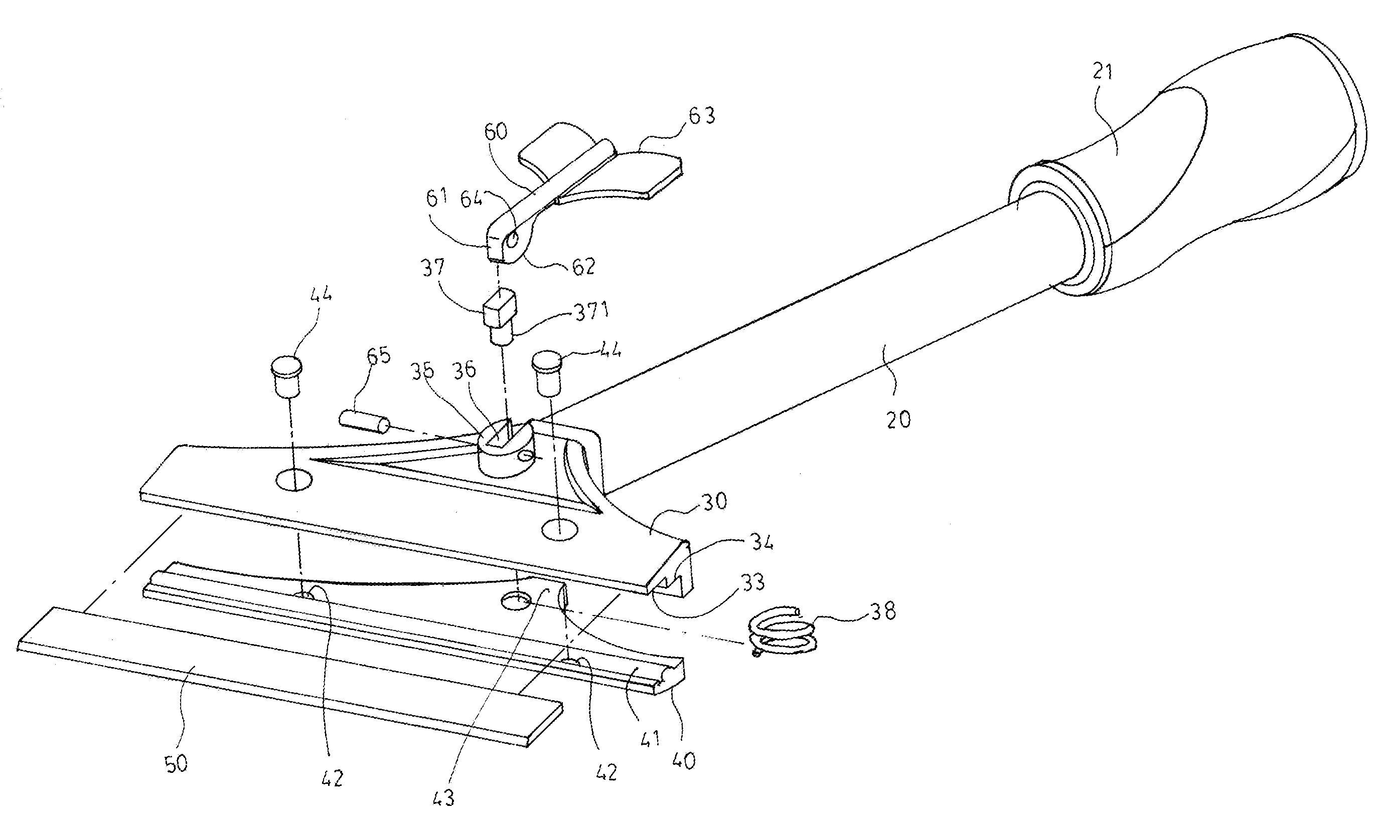
[0018]Please refer to FIG. 3, FIG. 4 and FIG. 5 for the disassembly diagram, assembly diagram and cross-sectional diagram for the scraping tool in the invention that can be assembled and replaced for scraper blade quickly. The scraping tool contains some components that are similar in a known scraping tool. They are a stick 20 for hand grasp and a scraping section assembly in the front. The back of the stick 20 is coupled with a grip 21. The scraping section assembly is composed of a scraping section 30. a jaw clamp 40, a scraper blade 50 and a control device (including a control level with wings, described as a control button 60 in the specification, a bolt 65, and a guide block 37 with a bottom pillar 371). On the jaw clamp 40 a rib 41 for attachment is laterally located at inner front edge and combination holes 42 are at two sides and an arm 43 of a suitable ...


PUM


Abstract

The invention is related to a scraping tool that can be assembled and replaced for scraper blade quickly. The scraping tool in general comprises a stick for hand grasp and a scraping section in the front. The invention mainly uses an arm of suitable length extended from the back end of a jaw clamp toward the middle. It uses fasteners to be located inside the groove in the back of the scraping section. The fastener is also used as pivot for the arm to swing back and forth. On the arm in the back of the jaw clamp, there is a control button that provides vertical pushing force in the back of the jaw clamp and allows strong clamping force in the front of the jaw clamp onto the scraper blade to achieve stable assembly and fast replacement for scraper blade.

Description

BACKGROUND OF THE INVENTION[0001]1. Field of the Invention[0002]The invention is related to a scraping tool to remove surface residues on wall or ground. Especially it refers to a scraping tool that can be assembled quickly and replaced for scraper blade.[0003]2. Description of the Prior Art[0004]To assure the flatness in replacing wallpaper or carpet, it is necessary to remove surface adhesive residues and adhesives completely. FIG. 1 and FIG. 2 show the structural disassembly diagram and assembly diagram for a known scraping tool. The scraping tool generally comprises a stick 10 for hand grasp and a scraping section 11 in the front. The back of the scraping section 11 forms a combination column 12 that can go into the stick 10 for connection. In the front of the scraping section 11 there is a jaw 13 and a clamp 14 that with several screws 17 run between a jaw 13 and a jaw clamp 15. A scraper blade 16 is put in the clamp 14 and protrudes forward. Therefore, a user can grasp the two...

Claims


Application Information

Patent Timeline
Patent Type & Authority Patents(United States)
IPC IPC(8): A47L13/02
CPCA47L13/08B26B5/00E04G23/006
Inventor LIN, WEN-CHEN
Owner LIN WEN CHEN
Why Eureka
Try Eureka