Pneumatic type feeder

A feeder and pneumatic technology, applied in the field of pneumatic feeders, can solve the problems of high cost of building a feeding table, high labor intensity for feeding, and limited throwing area, and achieves saving feed, high work efficiency, and throwing area. big effect

Inactive Publication Date: 2012-01-04
金湖小青青机电设备有限公司
View PDF4 Cites 7 Cited by
  • Summary
  • Abstract
  • Description
  • Claims
  • Application Information

AI Technical Summary

Problems solved by technology

[0003] When the existing feeding machine is in use, there are the following problems: 1. It needs to be fixed on the feeding platform of the pond, and the construction cost of the feeding platform is high; 200 kg, the feed box is too small, relying on manual feed addition, the feeding labor intensity is high; 3. The feeding machine can only spread feed within a certain angle range, and the spreading area is limited

Method used


Image

  • Pneumatic type feeder
  • Pneumatic type feeder

Examples


Embodiment Construction

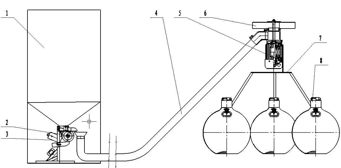
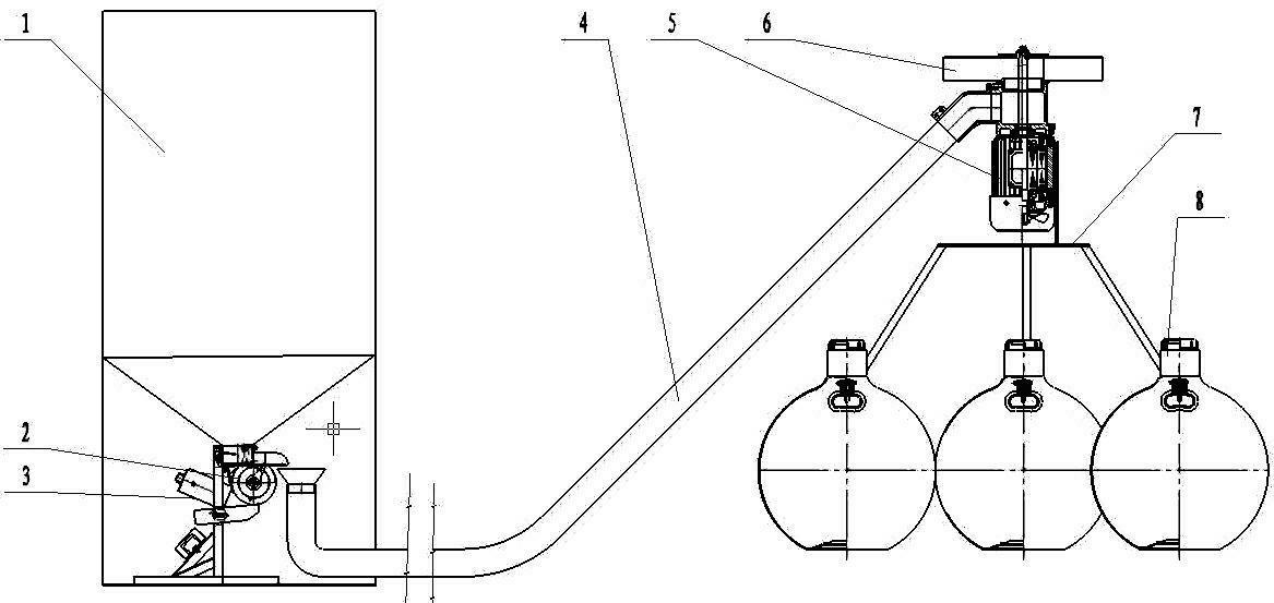
[0012] Such as figure 1 As shown, the pneumatic feeding machine includes a pneumatic motor 5, a rotating throwing tray 6, a feed delivery pipe 4, a material box 1, a feeder 2, a controller 3, a bracket 7 and a floating body 8, and the floating body is installed under the bracket 7 8. Install the air motor 5 above the bracket 7, the rotating throwing disc 6 is connected to the air motor 5, one end of the feed conveying pipe 4 is connected with the air motor 5 and runs through the rotating throwing disc 6, the other end of the feed conveying pipe 4 Through the distributor 2, the distributor 2 is installed at the outlet of the material box 1, and the controller 3 is installed on the material box 1, and the controller 3 is connected to the pneumatic motor 5 and the distributor 2.

[0013] Wherein, the length of the feed conveying pipe 4 is adjusted according to the conveying distance.

[0014] Wherein, the volume of the material box 1 can be set according to the needs of users. ...


PUM


Abstract

The invention discloses a pneumatic type feeder. The pneumatic type feeder comprises a pneumatic motor (5), a rotary throwing disc (6), a fodder conveying pipe (4), a fodder box (1), a distributor (2), a controller (3), a bracket (7) and a floating body (8); the floating body (8) is installed under the bracket (7) and the pneumatic motor (5) is installed above the bracket (7); the rotary throwing disc (6) is connected with the pneumatic motor (5); one end of the fodder conveying pipe (4) is connected with the pneumatic motor (5) and is communicated with the rotary throwing disc (6), and the other end of the fodder conveying pipe (4) is communicated with the distributor (2); the distributor (2) is installed on a discharge hole of the fodder box (1), the fodder box (1) is equipped with the controller (3), and the controller (3) is connected with the pneumatic motor (5) and the distributor (2). The feeder provided by the invention has the advantages of simple structure, low cost, convenience in installation, high automatic degree, manual work saving, big throwing area and high work efficiency.

Description

technical field [0001] The invention relates to a feeding machine, in particular to a pneumatic feeding machine applicable to the field of aquaculture. Background technique [0002] The research and development of feeding machinery began in the mid-1980s, and until the mid-1990s, fish farmers realized that the use of feeding machines could improve feed utilization, increase production, and increase income, so production and sales began to increase significantly. In 2008, the annual output of various types of feeding machines in China is estimated to reach 160,000 units, which is second only to aerators. At present, the bait feeding methods of the feeding machine include centrifugal throwing, pneumatic feeding, and hydraulic feeding; the feeding methods mainly include vibration feeding, cage feeding, flap feeding, and funnel feeding. The models with mature technology and wide application are mainly feeding machines that adopt mechanical centrifugal feeding and mechanical vib...

Claims


Application Information

Patent Timeline
Patent Type & Authority Applications(China)
IPC IPC(8): A01K61/02
Inventor 张晓青赵建宝周勇张爱民
Owner 金湖小青青机电设备有限公司
Why Eureka
Try Eureka