Protection switch for heavy current power limitation quick action
A quick-action protection, high-current technology, applied to the power devices, load-hanging components, safety devices and other directions inside the switch, can solve the problems of inability to realize the direct protection of the main circuit and the inability to directly apply the high-current circuit of the main circuit.
- Summary
- Abstract
- Description
- Claims
- Application Information
AI Technical Summary
Problems solved by technology
Method used
Image
Examples
example 1
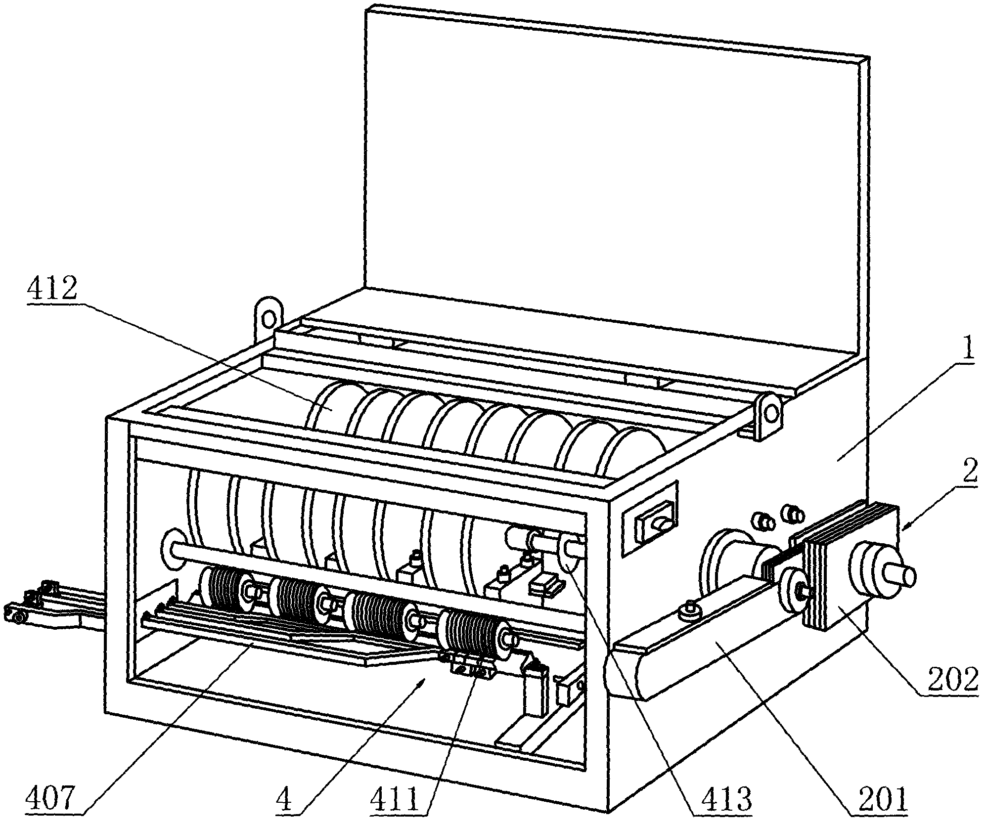
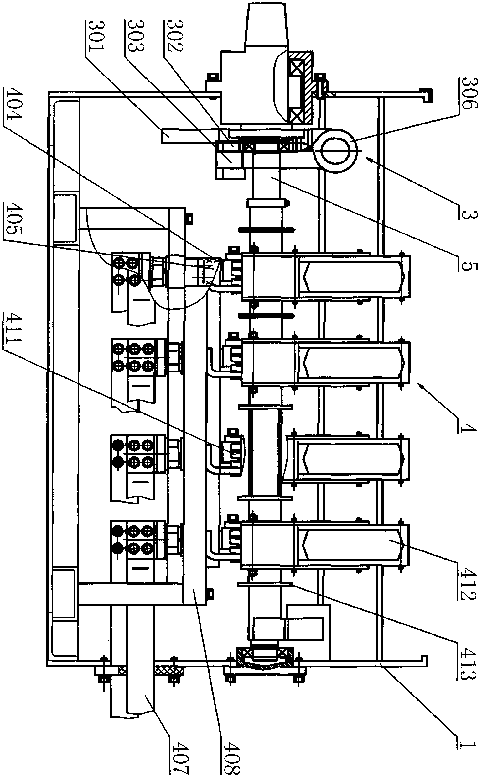
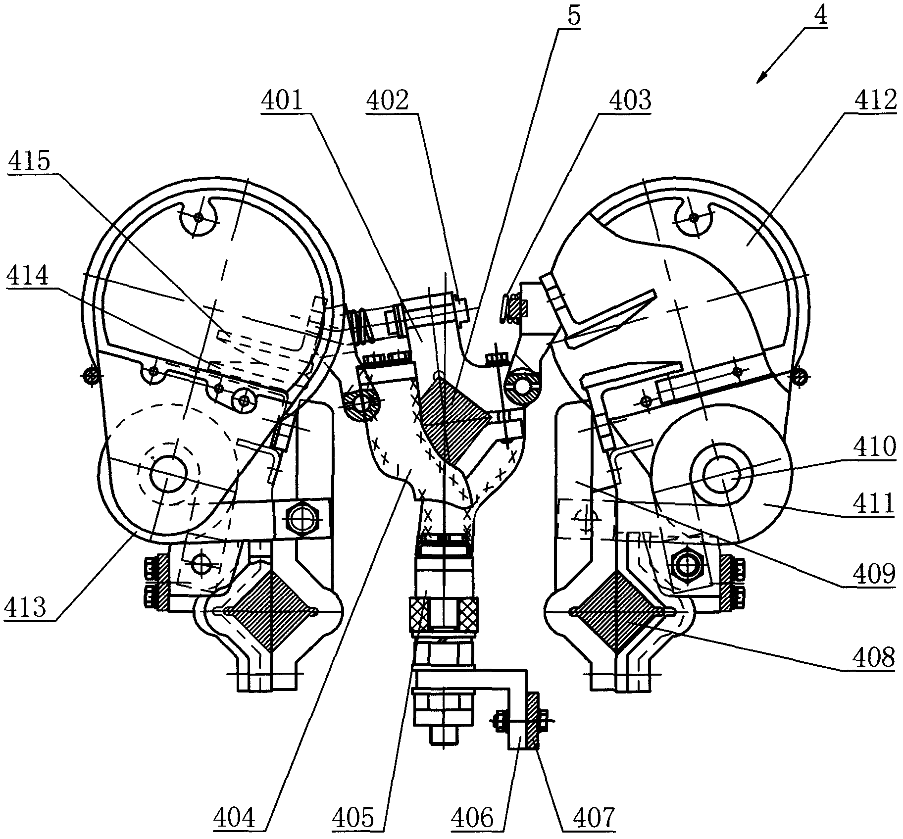
[0026] The high-current power limit snap-action protection switch of the present invention, such as Figure 1 to Figure 8 As shown, it includes a box body 1, a loss-of-force detection mechanism 2, a conversion energy storage mechanism 3, a contact system composed of four sets of contact mechanisms 4, and a main shaft 5. The main circuit uses four normally open and four normally closed contacts. The force detection mechanism 2 includes a balance arm 201 and a counterweight 202; the conversion energy storage mechanism 3 includes a converter 301, a cam 302, a pressure plate 303, a lever 304, a spring frame 305, a spring 306, and a roller 307; the contact mechanism 4 includes a contact bridge 401 , Spring support 402, booster spring 403, braided wire 404, terminal 405, connecting plate 406, bus bar 407, bracket 408, base 409, iron core 410, magnetic blowing coil 411, arc extinguishing cover 412, insulating gasket 413, Static contact 414 and moving contact 415.
[0027] Connect the p...
example 2
[0029] The high-current power limit snap-action protection switch of the present invention, in which the contact system is composed of two sets of contact mechanisms 4, that is, the main circuit adopts two normally open and two normally closed, in which the arc extinguishing cover 412 adopts an open arc extinguishing cover, and the static contact 414. The moving contact 415 and the braided wire 404 are made of metal copper. The rest of the structure and use are as described in Example 1, which can achieve the same effect as Example 1. It can be used for the protection of the main circuit with a rated current of 630A. The applicable current is also greater than the largest 16A current in the prior art.
PUM
 Abstract
Description
Claims
Application Information
 - R&D
- Intellectual Property
- Life Sciences
- Materials
- Tech Scout
- Unparalleled Data Quality
- Higher Quality Content
- 60% Fewer Hallucinations
Browse by: Latest US Patents, China's latest patents, Technical Efficacy Thesaurus, Application Domain, Technology Topic, Popular Technical Reports.
© 2025 PatSnap. All rights reserved.Legal|Privacy policy|Modern Slavery Act Transparency Statement|Sitemap|About US| Contact US: help@patsnap.com


