Switch self-locking structure

A self-locking structure and switch technology, applied in electrical switches, electrical components, circuits, etc., can solve the problems of unguaranteed reliability of self-locking switches and poor operating comfort, achieving good operating comfort, novel methods, and improved reliability. Effect

Inactive Publication Date: 2014-03-12
NANJING CHERVON IND
View PDF6 Cites 0 Cited by
  • Summary
  • Abstract
  • Description
  • Claims
  • Application Information

AI Technical Summary

Problems solved by technology

This kind of self-locking method adopts the rotation method, but the rotation axis of the self-locking trigger is perpendicular to the movement plane of the switch trigger, so the operation comfort is poor, and the reliability of the self-locking switch cannot be guaranteed

Method used


Image

  • Switch self-locking structure
  • Switch self-locking structure
  • Switch self-locking structure

Examples


Embodiment Construction

[0035] The present invention will be further described below in conjunction with the accompanying drawings. The following examples are only used to illustrate the technical solution of the present invention more clearly, but not to limit the protection scope of the present invention.

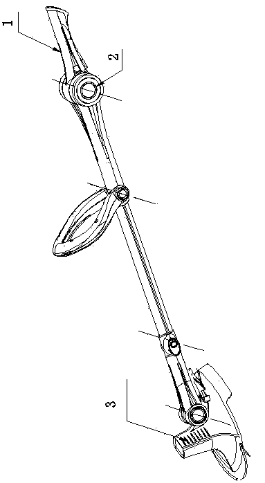
[0036] Such as figure 1 As shown, this embodiment takes the switch self-locking structure of the present invention applied to an electric tool as an example to describe the switch self-locking method of the present invention in detail. The electric tool includes a main handle 1 , a power source 2 and a working head 3 .

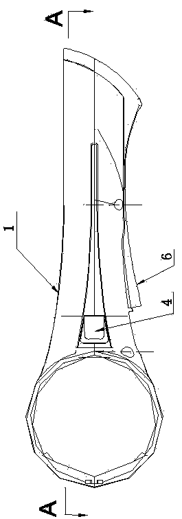
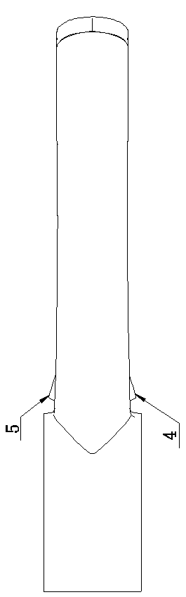
[0037] Such as figure 2 , image 3 , Figure 4 , Figure 5 with Figure 7 As shown, the self-locking structure is placed on the main handle 1, including a left self-locking trigger 4, a right self-locking trigger 5, a switch trigger 6 and a self-locking slider 7. The left self-locking trigger 4 and the right self-locking trigger 5 are arranged symmetrically and have the s...


PUM


Abstract

The invention discloses a switch self-locking structure which comprises a switch trigger and a self-locking structure, wherein the switch trigger is arranged on a main handle, is suitable for operation and can be displaced; the self-locking structure is arranged on the main handle and can lock or release the switch trigger; the self-locking structure at least comprises self-locking triggers and a self-locking sliding block, wherein the self-locking triggers are arranged symmetrically on the main handle; the sliding block can be pushed by the self-locking triggers and can slide axially along the main handle; and the self-locking sliding block and the switch triggers are respectively provided with an interlocking structure. According to the invention, the control of a main switch is realized through the rotary motion of the self-locking triggers, the self-locking triggers are dual-self-locking triggers, as long as any self-locking trigger is pressed, the other trigger is not required to act, the control to the switch can be realized; the switch can be controlled individually or simultaneously, which is more reliable; the plane of motion of a rotary shaft of any self-locking trigger is parallel with that of the switch trigger, and the operation comfort is better.

Description

technical field [0001] The invention relates to a switch self-locking structure, in particular to a switch self-locking structure of an electric tool. Background technique [0002] Switch self-locking is an essential function of most machines and is widely used. At present, the most common way is to lock and release the switch through the movement of the self-locking trigger. The pressing method and pressing feel are not ideal. Self-locking is a frequently used function, and the comfort of the self-locking trigger is greater. influences. [0003] As a self-locking structure of an electric tool in the prior art, when the trigger is in the locked position, the shearing part on the lock piece is engaged with the pin of the trigger, and the trigger rotation is limited at this time; when the trigger is in the released position, the operator pushes down the part , so that the arm rotates, the shear part is disengaged from the pin, and the rotary switch machine is turned on. Its...

Claims


Application Information

Patent Timeline
Patent Type & Authority Patents(China)
IPC IPC(8): H01H9/20
Inventor 过超群
Owner NANJING CHERVON IND
Why Eureka
Try Eureka