Corner connection

A corner connection and connector technology, which is applied in the direction of furniture connection, connection components, furniture parts, etc., to achieve the effect of flexible and simple assembly

Active Publication Date: 2012-01-04
PAUL HETTICH
View PDF9 Cites 10 Cited by
  • Summary
  • Abstract
  • Description
  • Claims
  • Application Information

AI Technical Summary

Problems solved by technology

Tolerances are necessary when pushing the panels in, so this corner connection

Method used


Image

  • Corner connection
  • Corner connection
  • Corner connection

Examples


Embodiment Construction

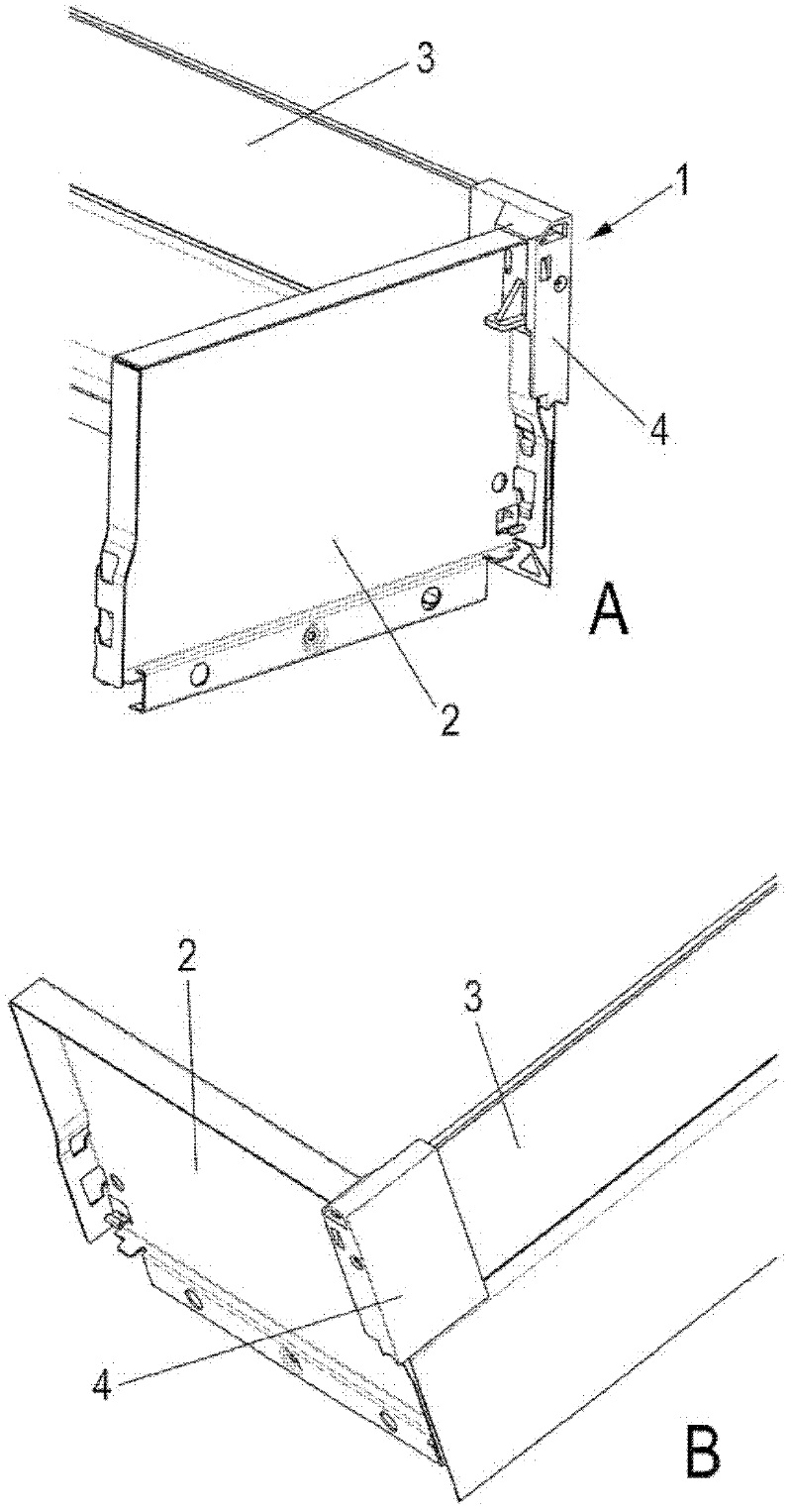
[0018] The corner connection 1 , in particular on a drawer, serves to connect the first wall element 2 with the second wall element 3 . The first wall element 2 can, for example, be configured as a rear wall of a drawer and be made of bent sheet metal. The second wall element 3 is designed as a side wall of the drawer or as an upper additional frame and consists of a hard material, in particular glass.

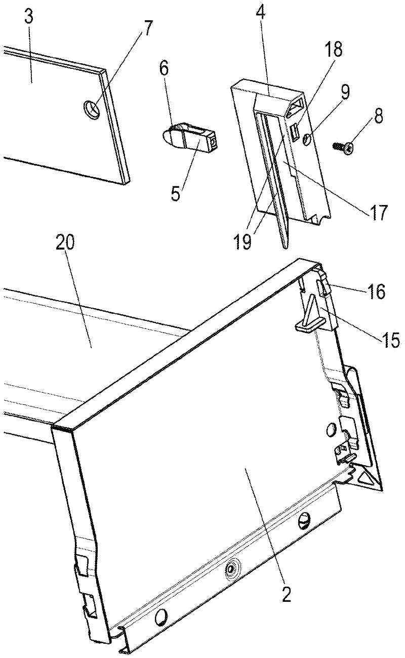
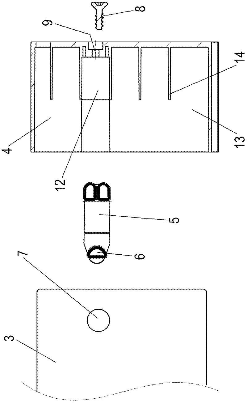
[0019] as in figure 2 As can be seen in FIG. 2 , the second wall element 3 is fastened to the connector 4 via the retaining element 5 . The holding element 5 is made of plastic as a clevis, wherein on the legs of the holding element 5 , on the inwardly facing side, a projection 6 is formed in each case, which can engage in an opening 7 in the second wall element 3 . The clevis can thus be inserted around the end side of the second wall element 3 in order to mount the second wall element 3 on the connector 4 .

[0020] as in image 3 As can be seen in FIG. 2 , the connecto...


PUM


Abstract

The invention relates to a corner connection (1), in particular for a drawer, having a first wall element (2) and a second wall element (3) arranged at an angle thereto, wherein there is a connector (4) that can be mounted on the first wall element (2) and has a receptacle for inserting the second wall element (3), characterized in that a holding element (5) can be inserted in the connector (4), by means of which the second wall element (3) can be fastened to the connector (4).

Description

technical field [0001] The invention relates to a corner connection, in particular for drawers, having a first wall element and a second wall element arranged at an angle to the first wall element, wherein a connector is provided, the connection The holder is pluggable onto the first wall element and has a receptacle for engaging the second wall element. Background technique [0002] DE 298 09 751 discloses an angle connector for flat panels, which has two angled receptacles which surround a flat panel at the end sides. An inwardly directed web is formed on each receptacle for guiding the plate. Tolerances are necessary when pushing the panels in, so that corner connections of this type are only suitable to a limited extent for movable furniture parts, such as drawers. [0003] For connecting a frame attachment to a rear wall in a drawer, a holding device is known from EP 1 516 561, which has a receptacle for inserting the frame attachment. The holding device is then conn...

Claims


Application Information

Patent Timeline
IPC IPC(8): A47B88/00
CPCA47B2088/0037A47B88/0014F16B12/46A47B88/941A47B2088/902
Inventor M・舒伯特C・施特尔策J・鲍姆
Owner PAUL HETTICH
Why Eureka
Try Eureka