
Method for locating multiple rays of a source with or without AOA by multi-channel estimation of the TDOA and FDOA

A positioning method, technology of reflection path, applied in positioning, directional multi-channel system using radio waves, direction finder using radio waves, etc.

Inactive Publication Date: 2012-01-04
THALES SA
View PDF2 Cites 19 Cited by
  • Summary
  • Abstract
  • Description
  • Claims
  • Application Information

AI Technical Summary

Problems solved by technology

Additionally, the disadvantage of these methods is that they assume prior knowledge of the ionosphere

Method used


Image

  • Method for locating multiple rays of a source with or without AOA by multi-channel estimation of the TDOA and FDOA
  • Method for locating multiple rays of a source with or without AOA by multi-channel estimation of the TDOA and FDOA
  • Method for locating multiple rays of a source with or without AOA by multi-channel estimation of the TDOA and FDOA

Examples


Embodiment Construction

[0050] modeling

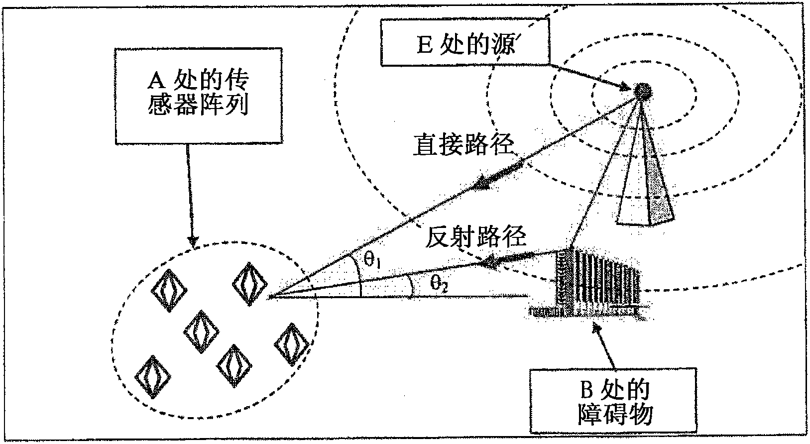
[0051] The method according to the invention involves, with the aid of an array comprising N elementary sensors, locating a source when there are direct paths and P≧1 temporally decorrelated paths. The path comes from reflections of P obstacles whose positions are known. figure 1 The case is shown for an array comprising N=6 sensors receiving both direct and reflected paths from the source. In this case P=1.

[0052] When the source has P-1 reflection paths, the expression for the signal received by the sensor array can be written as:

[0053] x ( t ) = x 1 ( t ) · · · ...


PUM


Abstract

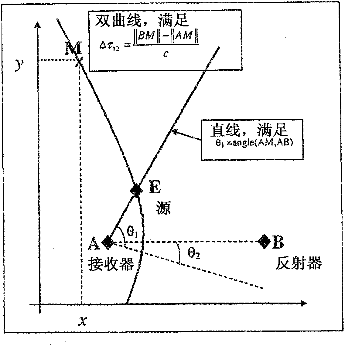
The invention relates to a method and to a system for locating a transmitter E transmitting a signal to a receiver A comprising N channels (N=1), the characteristics of said signal being unknown to the receiver and said signal being reflected by P reflectors Bi (P=1) with known positions, characterised in that the method comprises at least the following steps: Step 1: a step of multi-channel joint estimation / detection of the time differences of arrival or TDOA ti and the frequency differences of arrival or FDOA fi of each reflected ray; Step 2: a step of angular estimation of the direction Theta 1 of the direct ray of the signal emitted using a goniometry method; Step 3: a step of locating the position (x, y) of transmitter E in the plane at least on the basis of the pairs (ti, fi).

Description

technical field [0001] The invention relates to a method for locating a transmitter in two or three dimensions when there are multiple paths from a direct path and one or more reflected paths from obstacles whose positions are known. The path is received by a single multi-channel receiving system, the location of which is also known. The method according to the invention is based on a signal processing method. Background technique [0002] figure 1 An exemplary positioning system is shown that includes a multi-sensor receiving station at a known location A that receives a direct path and a path reflected from an obstacle at a known location B. These two received paths are transmitted by the source E whose position is to be located. The receiving station at position A receives the incident angle θ from the transmitting source E 1 The direct path of , and the reflection from the obstacle at B with an angle of incidence θ 2 path of. Locating the transmitter requires on th...

Claims


Application Information

Patent Timeline
Patent Type & Authority Applications(China)
IPC IPC(8): G01S5/12G01S3/74G01S5/02
CPCG01S5/0215G01S5/12G01S3/74G01S5/0218
Inventor C·耶蒙德A·费雷奥尔
Owner THALES SA
Learn More