Device for quickly mounting sonic nozzle

A sonic nozzle and fast technology, which can be used in hand-held tools, manufacturing tools, etc., can solve the problems of cumbersome mechanism, small space for air stagnation, high cost, etc., and achieve the effect of reasonable design, convenient installation of sonic nozzle and simple structure.

Inactive Publication Date: 2012-01-11
海盐弗洛德电子科技有限公司
View PDF6 Cites 1 Cited by
  • Summary
  • Abstract
  • Description
  • Claims
  • Application Information

AI Technical Summary

Problems solved by technology

However, since the sonic nozzle is installed in the stagnant air barrel, and the space of the stagnant air barrel is relatively narrow, and the mounting plate must be kept parallel to the sonic nozzle when installing and tightening the screws, so as to ensure the contact with the O-ring. High airtightness, it is very difficult to install the sonic nozzle, not only the labor intensity is high, but also the installation efficiency is extremely low, and the quality of each installation cannot be guaranteed. Thus affecting the detection of the sonic nozzle type gas meter detection device
At present, the more advanced method of installing the sonic nozzle in the detection device of the sonic nozzle type gas meter in foreign countries is to use the cylinder compression method, the mechanism is very cumbersome, the cost is high, it is not suitable for large-scale use, and the applicable area is narrow
[0003] At present, there is no device that can install the sonic nozzle conveniently, quickly and effectively, which not only brings great inconvenience to the installation of the sonic nozzle, but also reduces the detection efficiency and performance of the sonic nozzle type gas meter detection device

Method used


Image

  • Device for quickly mounting sonic nozzle
  • Device for quickly mounting sonic nozzle
  • Device for quickly mounting sonic nozzle

Examples


Embodiment Construction

[0023] The present invention will be further described in detail below in conjunction with the accompanying drawings and examples. The following examples are explanations of the present invention and the present invention is not limited to the following examples.

[0024] Example.

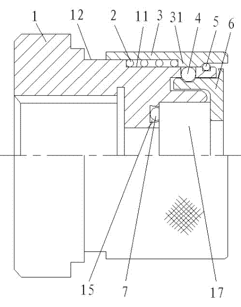
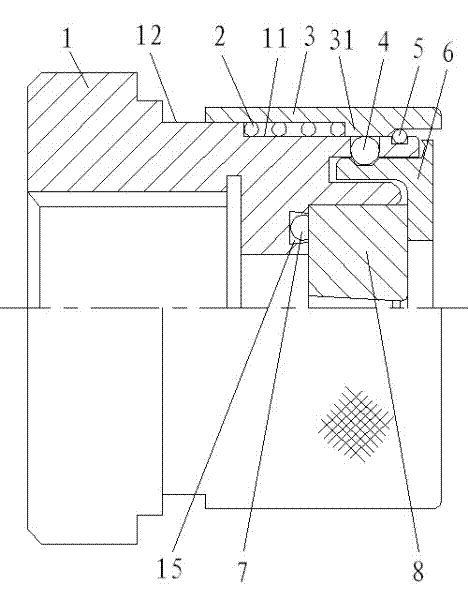
[0025] see Figure 1 to Figure 5 , the device for quickly installing the sonic nozzle in this embodiment includes a mounting block 1, a spring 2, a sliding sleeve 3, a movable positioning bead 4, a collar 5, a gland 6 and a sealing ring 7, wherein the material of the movable positioning bead 4 can be according to It needs to be selected in practice, for example, the movable positioning bead 4 can be made of steel. The sealing ring 7 can also be selected according to actual needs, such as the sealing ring 7 can be an O-ring structure.

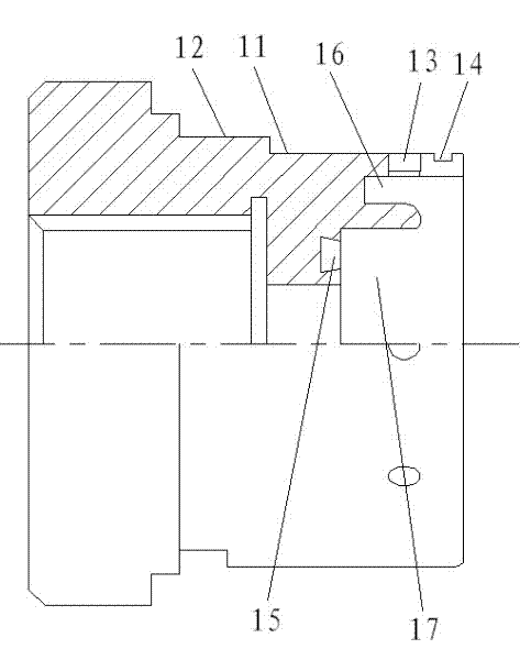
[0026] In this embodiment, the front end of the mounting block 1 is provided with a nozzle cavity 17 and an inner groove 16, and the outer wall of the mounting blo...


PUM


Abstract

The invention relates to a device for quickly mounting a sonic nozzle. According to the device, the sonic nozzle can be quickly arranged into a sonic nozzle type detection device for a gas meter. At present, a device for mounting a sonic nozzle conveniently, quickly and efficiently is not invented. The device comprises a mounting block, a spring, a sliding sleeve, movable positioning balls, a retainer ring and a gland, wherein a nozzle cavity and an inner groove are arranged at the front end of the mounting block; a first step and a second step are arranged on the outer wall surface of the mounting block; the spring is sleeved on the first step; the inner groove is positioned between the first step and the nozzle cavity; the first step is provided with a clamping groove and a through hole; the retainer ring is arranged in the clamping groove; a fixed ring provided with a groove on the outer wall surface is arranged on the gland and is inserted in the inner groove; the movable positioning balls are arranged in the through hole and the groove respectively; an inner lug boss is arranged on the inner wall of the sliding sleeve; the sliding sleeve is sleeved on the first step and the second step; and the inner lug boss is supported against the spring. The device has the advantages of reasonable structural design, convenience in use, high efficiency for mounting the sonic nozzle and favorable mounting quality.

Description

technical field [0001] The invention relates to a device for installing a sonic nozzle, in particular to a device for quickly installing a sonic nozzle. In the nozzle type gas meter detection device, the gas meter is detected. Background technique [0002] The sonic nozzle is one of the most important standard devices in the gas meter measurement and testing device. It has high sealing requirements for installation. Since it will be continuously polluted by the flowing gas during use, the sonic nozzle must be replaced and cleaned frequently. A fast, simple, reliable and convenient mechanism for installing the sonic nozzle is needed to meet this requirement. At present, the sonic nozzle is usually installed in the sonic nozzle type gas meter detection device by fixing the mounting plate with screws, so as to compress the sonic nozzle . However, since the sonic nozzle is installed in the stagnant air barrel, and the space of the stagnant air barrel is relatively narrow, and ...

Claims


Application Information

Patent Timeline
Patent Type & Authority Applications(China)
IPC IPC(8): B25B27/02
Inventor 汤有成
Owner 海盐弗洛德电子科技有限公司
Why Eureka
Try Eureka