Low-inertia ejection mechanism of all-electric injection machine

An injection molding machine, all-electric technology, applied in the field of low-inertia injection mechanism of all-electric injection molding machine, can solve the problems of large injection inertia of injection mechanism and inability to achieve precise control, and achieve the effect of prolonging service time and low injection inertia

Inactive Publication Date: 2012-01-11
NINGBO SHUANGMA MASCH IND CO LTD
View PDF2 Cites 6 Cited by
  • Summary
  • Abstract
  • Description
  • Claims
  • Application Information

AI Technical Summary

Problems solved by technology

The injection mechanism is basically composed of a pre-plastic part and an injection part. When the injection mechanism is working, the plastic particles are first plasticized by the pre-plastic part, and then the plasticized plastic is extruded from the injection part. When working, it is often necessary to drive the pre-molding part to do reciprocating motion together, resulting in a large injection inertia of the injection mechanism, which cannot achieve precise control

Method used


Image

  • Low-inertia ejection mechanism of all-electric injection machine
  • Low-inertia ejection mechanism of all-electric injection machine
  • Low-inertia ejection mechanism of all-electric injection machine

Examples


Embodiment Construction

[0015] The present invention will be further described in detail below in conjunction with the accompanying drawings and embodiments.

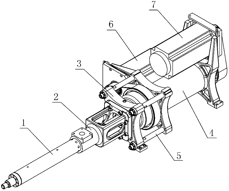
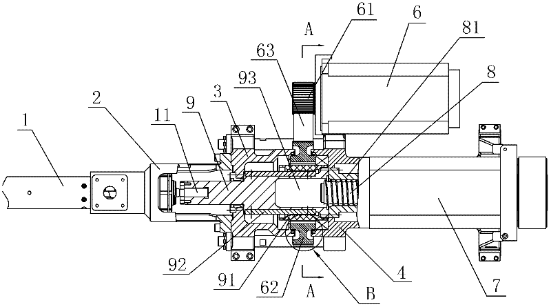
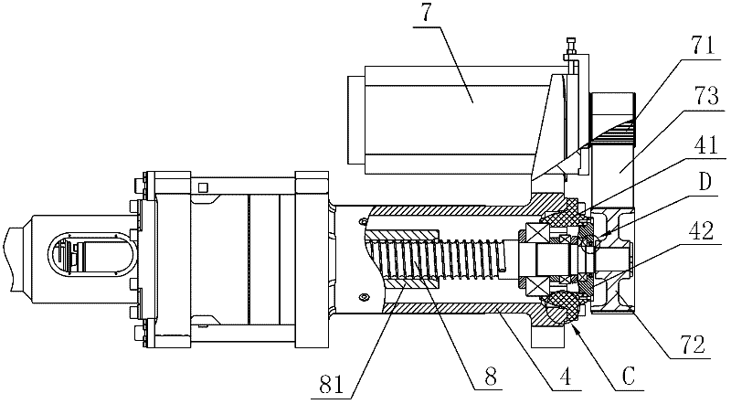
[0016] As shown in the figure, a low-inertia injection mechanism of an all-electric injection molding machine includes a barrel assembly 1, a hopper seat 2, a pre-molding seat 3, an injection molding seat 4, a pre-molding drive device, and an injection drive device. The hopper seat 2 is fixedly connected to the On the pre-molding seat 3, the pre-molding seat 3 and the injection molding seat 4 are fixedly connected by a connecting rod 5, and the pre-molding driving device includes a pre-molding motor 6, a pre-molding driving wheel 61, a pre-molding driven wheel 62 and a pre-molding transmission belt 63, The injection driving device includes an injection motor 7, an injection driving wheel 71, an injection driven wheel 72, and an injection transmission belt 73. The pre-molding motor 6 and the injection motor 7 are respectively fixedly installed o...


PUM


Abstract

The invention discloses a low-inertia ejection mechanism of all-electric injection machine, comprising a charging barrel assembly, a hopper base, a pre-plastic base, an injection molding base, a pre-plastic drive unit, and an ejection drive unit, wherein, the hopper base is fixed connected with the pre-plastic base, the pre-plastic base is fixed connected with the injection molding base through a connecting rod. The invention is characterized in that: a screw rod is connected with the internal shaft of the pre-plastic base, the screw rod is connected with the ejection drive unit, the internal shaft of the pre-plastic base is connected with a thrust base which is coaxial with the screw rod, the front end of the thrust base is fixed connected with the screw which is arranged in the charging barrel assembly, the rear portion of the thrust base is respectively connected with the pre-plastic drive unit and the screw rod, and the thrust base is provided with an ejection rotation isolation unit. The advantages of the invention comprises that: because the thrust base is provided with an ejection rotation isolation unit, when extrusion of the plasticized plastic from the charging barrel assembly is needed, the ejection drive unit works and push the screw to move forward or unclench backward through the screw rod and the thrust base, at the moment, the pre-plastic drive unit dose not take reciprocating motion with the thrust base, so as to let the ejection inertia of the ejection mechanism be low, so that the high speed fine control of the ejection mechanism is realized.

Description

technical field [0001] The invention relates to an injection molding machine, in particular to a low-inertia injection mechanism of an all-electric injection molding machine. Background technique [0002] At present, the plastic products on the market are basically injection molded by the injection machine. The injection molding machine mainly includes two parts: the injection mechanism and the clamping mechanism. The plasticization and injection of the plastic particles are completed through the injection mechanism. The injection mechanism is basically composed of a pre-plastic part and an injection part. When the injection mechanism is working, the plastic particles are first plasticized by the pre-plastic part, and then the plasticized plastic is extruded from the injection part. When working, it is often necessary to drive the pre-molding part to reciprocate together, resulting in a large injection inertia of the injection mechanism, which cannot achieve precise control...

Claims


Application Information

Patent Timeline
IPC IPC(8): B29C45/48B29C45/50B29C45/58B29C45/83
Inventor 谭树发刘玉鹏胡宝全邓俊钧喻鹏康晓军胡进旺
Owner NINGBO SHUANGMA MASCH IND CO LTD
Why Eureka
Try Eureka