Pressure reducing valve

A pressure reducing valve and valve body technology, which is applied in the field of pressure reducing valves, can solve the problems of not meeting the requirements of water flow, narrowness, etc., and achieve the solution of asymmetrical elastic decay, stable water outlet without vibration, and avoiding water hammer impact Effect

Active Publication Date: 2013-03-20
沁幸富氢科技(广东)有限公司
View PDF3 Cites 0 Cited by
  • Summary
  • Abstract
  • Description
  • Claims
  • Application Information

AI Technical Summary

Problems solved by technology

But because the rubber plug 13 is located in the water inlet hole of the 1 / 2 inch interface of the pressure reducing valve, after subtracting the outer diameter of the rubber plug, the passage of the water flow seems very narrow, so it cannot reach 10 per minute for this reason. - Reason for flux requirement of 20 liters of water flow

Method used


Image

  • Pressure reducing valve
  • Pressure reducing valve
  • Pressure reducing valve

Examples


Embodiment 2

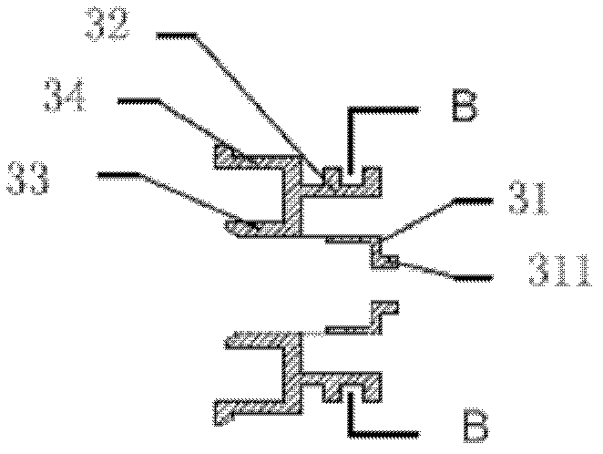
[0036] On the basis of the above-mentioned implementation, this embodiment provides another matching method for the connection structure between the valve core seat and the front cover, as follows:

[0037] see Figure 9 , the inner cavity of the front cover is provided with an internal thread, and the outer circular wall of the ring part 32 of the valve core seat is provided with an internal thread suitable for the thread of the inner cavity of the front cover, and an O-ring is arranged above the valve part of the valve core seat 5. The valve part of the valve core seat squeezes the O-ring 5 against the top of the inner cavity of the front cover, so that an end face seal is formed between the front valve cavity and the valve core seat. Due to the threaded connection structure, the valve core seat can cancel the outer base which plays a role of fixed installation, and correspondingly cancel the groove and clamping hole on the front cover.

[0038] Furthermore, since the water...


PUM


Abstract

The invention discloses a pressure reducing valve, which comprises a front cover, a rear cover and a valve core component, wherein the end parts of the front cover and the rear cover are provided with external thread joints; the valve core component comprises a valve core seat, a valve core shaft, a diaphragm and a spring; the valve core seat is supported against the valve core shaft to axially slide; the spring is sleeved on the valve core shaft; a valve cavity is hermetically separated from a water outlet cavity by the diaphragm; a rubber plug is arranged in a valve part of the valve core seat; and a water flow passage is formed in the valve core shaft. The pressure reducing valve provided by the invention is a small-interface large-flux pressure reducing valve which can meet I / 2 interface requirement and large-flow requirement; the valve core component has a single-spring structure and is not required to be repeatedly adjusted during use; the problem of asymmetric elastic force attenuation of a double-spring structure is completely solved; water outlet pressure is automatically adjusted; the valve is stable and reliable in use; convenience is brought to a user; and after-sale workload is also greatly reduced. The valve core component is in a clamping connection mode on various parts; screws are not arranged in the valve body for connection; the connection structure is skillful in design and easy and convenient to assemble; and the material consumption and the cost are reduced.

Description

technical field [0001] The present invention relates to a pressure reducing valve, more specifically, relates to a pressure reducing valve used in civil water supply system. Background technique [0002] With the development of economy and society, especially after my country's reform and opening up, urban commercial housing construction has sprung up like mushrooms, among which luxurious and fashionable villas have emerged in many provinces and cities in China, reflecting that people's living index has reached the level of developed countries. With the rapid development of urbanization and industrialization, the pollution of water resources may continue to worsen. Urban and rural people's awareness of health care continues to increase, and the demand for healthy drinking water is increasing. Household water purifiers have become a sunrise product for the coordinated development of man and nature. Its environmental protection, hygiene, economy and convenience are more and mo...

Claims


Application Information

Patent Timeline
Patent Type & Authority Patents(China)
IPC IPC(8): F16K17/00F16K47/02F16K47/04
Inventor 金祖贻
Owner 沁幸富氢科技(广东)有限公司
Why Eureka
Try Eureka