High-speed model horizontal tail concentric-square-shaped angle-changing device with high horizontal tail layout

A flat tail and layout technology, applied in the field of high-speed model flat tail "back" deformation angle devices, can solve problems such as damage and affecting the accuracy of model test results.

Active Publication Date: 2021-09-07
INST OF HIGH SPEED AERODYNAMICS OF CHINA AERODYNAMICS RES & DEV CENT
View PDF13 Cites 0 Cited by
  • Summary
  • Abstract
  • Description
  • Claims
  • Application Information

AI Technical Summary

Problems solved by technology

One is that during the test, the horizontal tail will generate a large aerodynamic load and then transmit it to the vertical tail through the angle-changing device. On the vertical tail with a high connection position and a thin thickness, the angle-changing device will bear large forces and moments, which may If it is damaged, there is a safety risk; the second is whether the designed horizontal tail angle-changing device can ensure that the aerodynamic shape of the connection between the horizontal tail and the vertical tail is not damaged. If safety is considered too much, the designed horizontal tail angle-changing device will protrude from the original aerodynamic shape , affecting the accuracy of the wind tunnel test results of the model

Method used


Image

  • High-speed model horizontal tail concentric-square-shaped angle-changing device with high horizontal tail layout
  • High-speed model horizontal tail concentric-square-shaped angle-changing device with high horizontal tail layout
  • High-speed model horizontal tail concentric-square-shaped angle-changing device with high horizontal tail layout

Examples


Embodiment Construction

[0038] In order to make the purpose, technical solutions and advantages of the embodiments of the present application clearer, the technical solutions in the embodiments of the present application will be clearly and completely described below in conjunction with the drawings in the embodiments of the present application. Apparently, the described embodiments are some of the embodiments of the present application, but not all of them.

[0039] The technical solutions in this application are described below in conjunction with the accompanying drawings.

[0040] This embodiment provides a high-speed model horizontal tail "back" deformation angle device with a high horizontal tail layout.

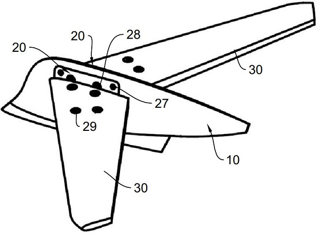
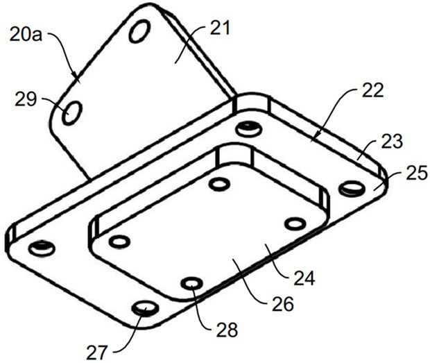
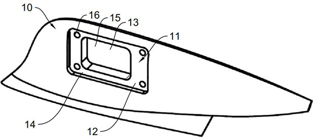
[0041] See Figure 1-Figure 3 , figure 1 It is a schematic diagram of the work of the high-speed model flat tail "back" deformation angle device of the high flat tail layout in this embodiment, figure 2 It is the schematic diagram of vertical tail 10 in the present embodiment, image 3It...


PUM


Abstract

The invention discloses a high-speed model horizontal tail concentric-square-shaped angle-changing device with high horizontal tail layout. The device comprises a vertical tail and a plurality of variable angle block pairs. A concentric-square-shaped connecting structure is formed on the vertical tail, the concentric-square-shaped connecting structure is provided with a first connecting part and a second connecting part, and the first connecting part and the second connecting part are in a step shape. The variable angle block comprises a lug piece and a concentric-square-shaped installation structure, the concentric-square-shaped installation structure is provided with a first installation part and a second installation part, the first installation part and the second installation part are in a step shape and correspond to the first connection part and the second connection part in an embedded mode, and the lug piece is connected to the first installation part. The deflection angles of the lugs of the same variable angle block pair are the same, and the deflection angles of the lugs of different variable angle block pairs are different. The vertical tail is configured to be detachably matched with any one variable angle block pair, the two variable angle blocks in the variable angle block pair are in an embedded shape and detachably connected to the two sides of the vertical tail, the first installation part is detachably connected with the first connecting part, and the second installation part is detachably connected with the second connecting part.

Description

technical field [0001] This application relates to the technical field of aircraft model wind tunnel testing, in particular, to a high-speed model flat tail "back" deformation angle device with a high flat tail layout. Background technique [0002] The high-level tail is a common aerodynamic layout of aircraft, which is widely used in business jets and large transport aircraft. High-speed wind tunnel tests will be carried out during the research and development process of aircraft with high horizontal tail layout, and the test of variable horizontal tail deflection will be carried out in the high-speed wind tunnel test to obtain the influence of horizontal tail deflection on the aerodynamic characteristics of the aircraft. In this process, the change of the deflection of the horizontal tail is realized through the angle-changing device, that is, the angle-changing device connects the horizontal tail and the vertical tail and realizes the change of the angle of the horizontal...

Claims


Application Information

Patent Timeline
IPC IPC(8): G01M9/08B64F5/60
CPCG01M9/08B64F5/60
Inventor 魏志吴军强陈学孔杨何发高亦非马晓永彭鑫唐世勇
Owner INST OF HIGH SPEED AERODYNAMICS OF CHINA AERODYNAMICS RES & DEV CENT
Why Eureka
Try Eureka