Air conditioner and air-conditioner indoor machine

A technology for indoor units and air conditioners, applied in the direction of airflow control components, etc., can solve the problems of greatly affecting the air volume, affecting the performance of the air conditioner, and reducing the air outlet area of ​​the air outlet, etc., to achieve the effect of automatic air guiding and automatic sweeping

Active Publication Date: 2012-01-11
GREE ELECTRIC APPLIANCES INC
View PDF5 Cites 19 Cited by
  • Summary
  • Abstract
  • Description
  • Claims
  • Application Information

AI Technical Summary

Problems solved by technology

[0002] The current air supply method of the air conditioner is: a wind guide plate is installed at the air outlet of the air conditioner, and the sweeping blades are placed on the upper or lower side of the air duct wall of the air conditioner outlet to jointly realize the air guide control in the up-down direction and left-right direction; In this ai

Method used


Image

  • Air conditioner and air-conditioner indoor machine
  • Air conditioner and air-conditioner indoor machine
  • Air conditioner and air-conditioner indoor machine

Examples


Embodiment 1

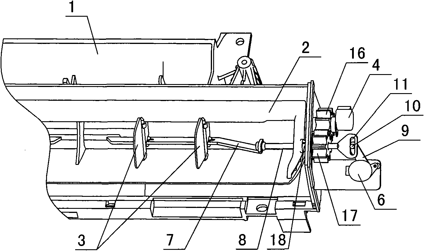
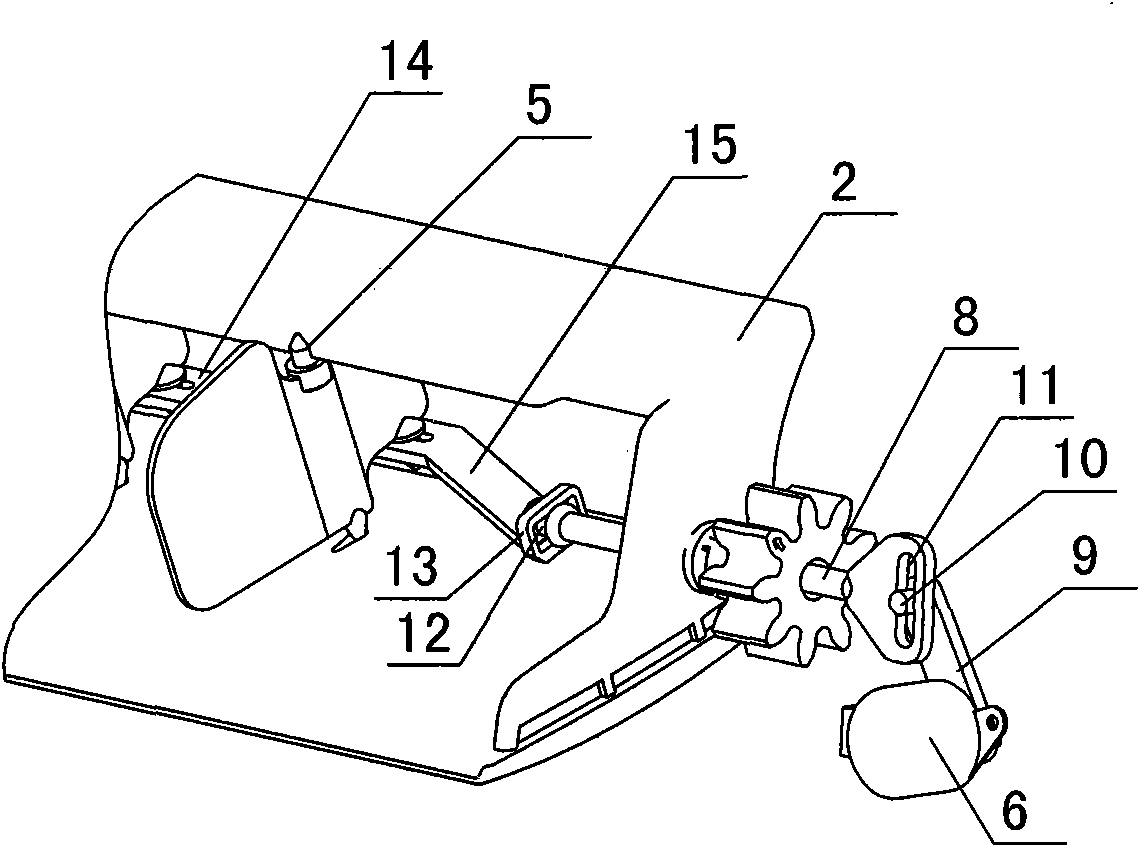
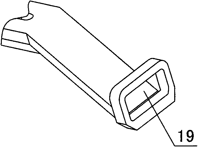
[0031] like figure 1 , figure 2 and image 3 As shown, an indoor unit of an air conditioner includes an indoor unit casing 1, an air deflector 2 and a sweeping vane 3, and the first end and the second end of the air deflector 2 are respectively connected to the indoor casing through a horizontal rotating shaft 18. On the first end and the second end of the body 1, the sweeping blades 3 are movably connected to the wind deflector 2 through the blade rotating shaft 5, and the wind deflector 2 guides the driving mechanism 4 (in this embodiment, the deflector The wind driving mechanism 4 is connected by the wind guide motor), and also includes a first connecting rod 7 and a second connecting rod 8 that are movably connected. After the second connecting rod 8 passes through the sliding hole, it is connected with the sweeping wind driving mechanism 6 (in this embodiment, the sweeping wind driving mechanism 6 is a sweeping wind motor).

[0032] In this embodiment, the wind deflec...

Embodiment 2

[0039] like Figure 4As shown, the difference between this embodiment and Embodiment 1 is that the sliding hole is arranged in the horizontal shaft at the first end of the wind deflector 2, the first connecting rod 7 is connected with the sweeping blade 3, and the horizontal shaft The center of 18 is provided with a sliding hole, and the second connecting rod 8 passes through the sliding hole and is connected with the sweeping drive mechanism 6 for driving the sweeping blade 3, and the second end of the wind deflector 2 passes through the horizontal shaft 18 It is connected with the wind guide driving mechanism 4 for driving the wind guide plate 2 . In this embodiment, the wind sweeping driving mechanism 6 and the wind guiding driving mechanism 4 are installed at both ends of the wind deflecting plate 2 respectively, and its working principle is the same as that of the first embodiment.

Embodiment 3

[0041] like Figure 5 As shown, the difference between this embodiment and the second embodiment is that this embodiment also includes a gear 20, and a rack 21 meshing with the gear 20 is provided at the end of the second connecting rod 8, and the sweeping wind The driving mechanism 6 is a blower motor, and the output shaft of the blower motor is connected with the gear 20 . Through the gear 20 and the rack 21 , the rotational motion of the wind sweeping motor can also be converted into a left and right reciprocating motion, thereby driving the swing of the wind sweeping blades 3 .


PUM


Abstract

The invention discloses an air conditioner and an air-conditioner indoor machine. The air-conditioner indoor machine comprises an indoor-machine shell, a wind-guiding plate, a wind-sweeping vane, a first connecting rod and a second connecting rod, wherein the first end and the second end of the wind-guiding plate are respectively and movably connected onto the first end and the second end of the indoor-machine shell through a horizontal rotating shaft, the wind-sweeping vane is movably connected onto the wind-guiding plate through a vane-rotating shaft, and the wind-guiding plate is connectedwith a wind-guiding driving mechanism; and the first connecting rod and the second connecting rod are movably connected, the first connecting rod is connected with the wind-sweeping vane, the center of the horizontal rotating shaft is provided with a sliding hole, and the second connecting rod is connected with a wind-sweeping driving mechanism after penetrating through the sliding hole. Through the air-conditioner indoor machine, the influence of the wind-sweeping vane on the wind-discharging area can be avoided, and the automatic wind guide and the automatic wind sweeping of the air conditioner can be realized.

Description

technical field [0001] The invention belongs to the field of air conditioners, and in particular relates to an air conditioner and an indoor unit of the air conditioner. Background technique [0002] The current air supply method of the air conditioner is: a wind deflector is installed at the air outlet of the air conditioner, and the sweeping blades on the upper or lower side of the air duct wall of the air conditioner air outlet jointly realize the air guide control in the up-down direction and left-right direction; In this air supply mode, the air supply in the left and right directions can be divided into manual and automatic. At this time, the sweeping blades are inclined in the air duct, so that the actual air outlet area of ​​the air outlet is greatly reduced, which has a great impact on the air volume, and then affects the performance of the air conditioner. Contents of the invention [0003] The purpose of the present invention is to overcome the defects of the p...

Claims


Application Information

Patent Timeline
IPC IPC(8): F24F13/12
Inventor 杨洪永
Owner GREE ELECTRIC APPLIANCES INC
Why Eureka
Try Eureka