Limiting the continuous mode of a power converter

a power converter and continuous mode technology, applied in the field of power converters, can solve the problem of forming a bi-voltage converter (220 or 110 volts) and is forbidden

Inactive Publication Date: 2006-05-30
STMICROELECTRONICS SRL
View PDF12 Cites 20 Cited by
  • Summary
  • Abstract
  • Description
  • Claims
  • Application Information

AI Technical Summary

Benefits of technology

[0019]A first solution would be to have the restarting of the starting circuit of the converter switch be conditioned by a complete demagnetization of the auxiliary winding. By detecting the end of the demagnetization, it would be ensured that the converter no longer is in a continuous mode operation (non demagnetized at each cycle). The control of the auxiliary voltage, that is, of the demagnetization point, guarantees the control of the current in the switch. The frequency of circuit 10 can thus be decreased, which results in less current peaks. Further, the problem of switching to a continuous mode is suppressed since the converter is maintained in a discontinuous mode.
[0022]Thus, the present invention also aims at providing a solution which is compatible with an integration of the control circuit of the switch, more specifically, with an integrated circuit of VIPER type and the corresponding number of terminals. The present invention also aims at providing a solution that enables operation in continuous mode of the converter.

Problems solved by technology

Another disadvantage is that by forbidding an operation in continuous mode, the forming of a bi-voltage converter (220 or 110 volts) is also forbidden.

Method used


Image

  • Limiting the continuous mode of a power converter
  • Limiting the continuous mode of a power converter
  • Limiting the continuous mode of a power converter

Examples


Embodiment Construction

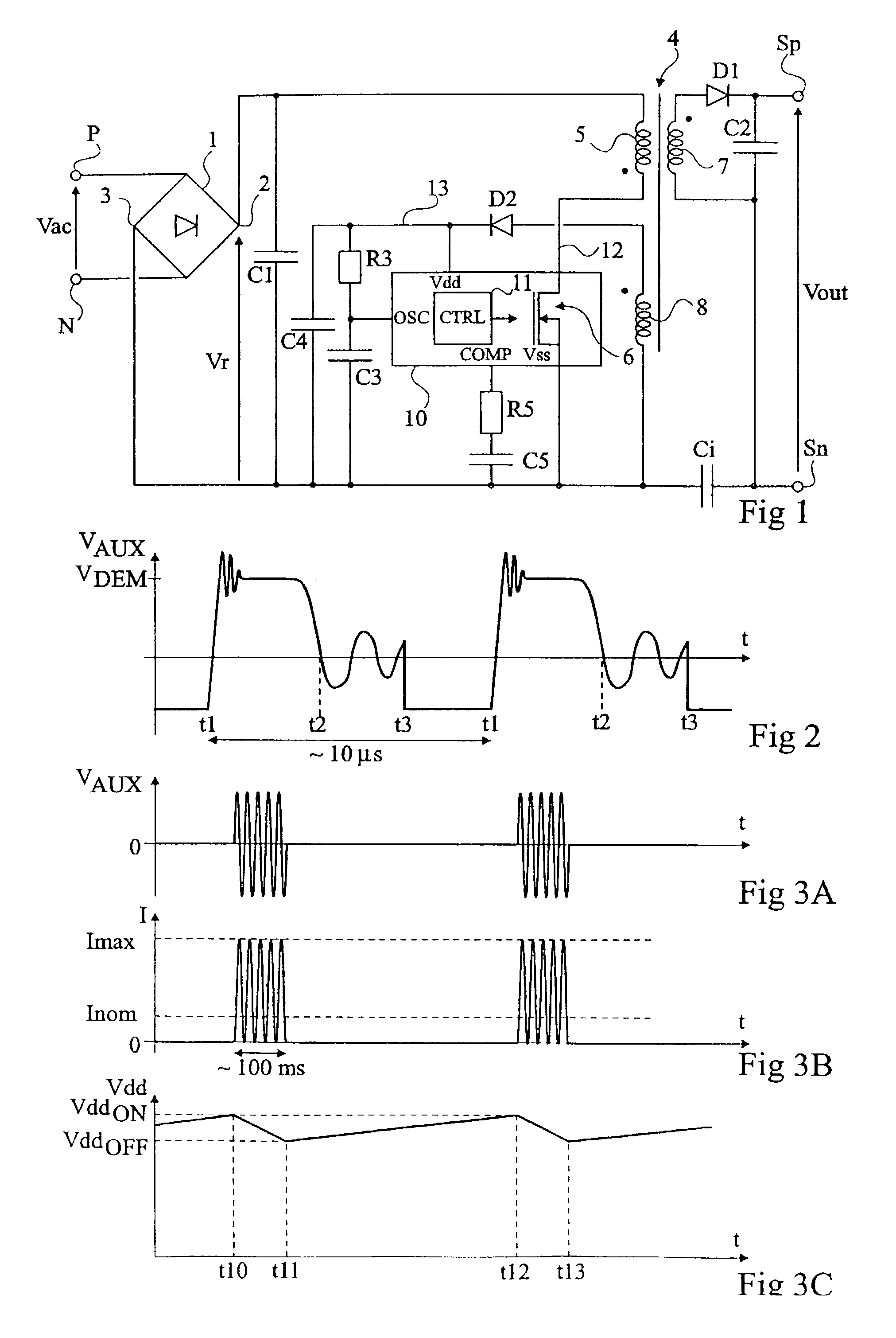
[0034]The same elements have been designated with the same references in the different drawings. FIGS. 2, 3A to 3C, 5A to 5F and 6 are not to scale. For clarity, only those elements of the converter which are necessary to the understanding of the present invention have been shown in the drawings and will be described hereafter. In particular, the internal structure of a VIPER-type integrated circuit has only been detailed for the elements useful to the discussion of the present invention. The rest of its structures, as well as the operation of such a circuit, is known.

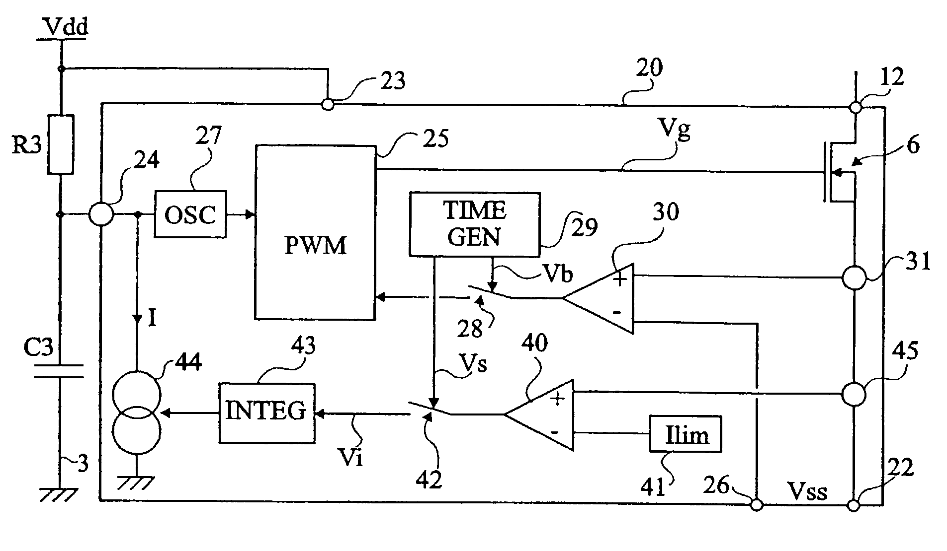
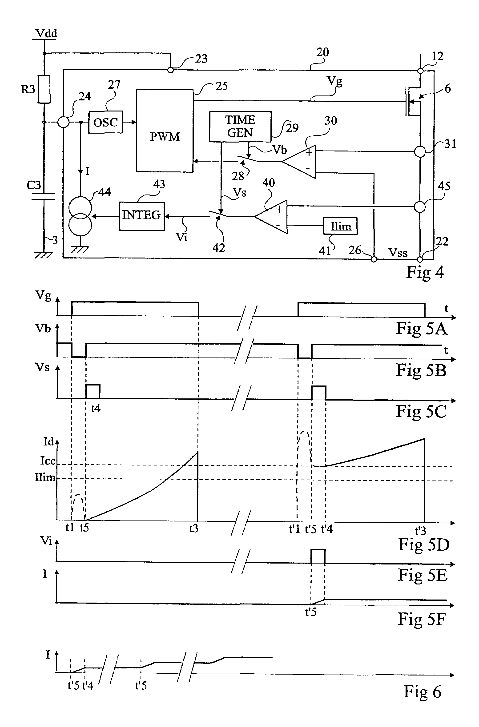
[0035]FIG. 4 shows an embodiment of a control circuit of a supply voltage cut-up switch according to the present invention. The example of FIG. 4 relates to the case of a circuit 20 integrating switch 6 (for example, an N-channel MOS transistor). This circuit is comprised, for example, of the components integrated in a known VIPER circuit.

[0036]As previously, and although this is not shown in FIG. 4, a circuit accordin...


PUM


Abstract

The invention concerns a control circuit (20) of a switch (6) chopping a voltage supply of a primary winding of a power converter transformer, comprising means (45) for detecting the current in the switch in closed state after a predetermined time following each closure of said switch, and a comparator (40) of said current relative to a threshold (Ilim), the result of said comparator being taken into account for a predetermined time interval close to the beginning of a closing cycle of said chopping switch.

Description

BACKGROUND OF THE INVENTION[0001]1. Field of the Invention[0002]The present invention relates to the field of power converters of low voltage switched-mode power supply type. The present invention more specifically applies to isolated power supplies, that is, supplies that have no common point between the input voltage (for example, the A.C. supply system) and the regulated D.C. output voltage. The isolation is obtained by means of a transformer having a primary winding associated with a pulse-width modulation controlled switch, and having a secondary winding associated with a diode and with a capacitor providing the output voltage.[0003]2. Discussion of the Related Art[0004]FIG. 1 shows a conventional example of a switched-mode power supply of the type to which the present invention applies. Two input terminals P, N receive an A.C. voltage Vac, for example, the mains voltage. Voltage Vac undergoes a rectification, for example a fullwave rectification by means of a diode bridge 1. T...

Claims


Application Information

Patent Timeline
Patent Type & Authority Patents(United States)
IPC IPC(8): H02M3/335H03K3/00H02M3/28H03K17/082
CPCH03K17/0822H02M3/33507
Inventor BAILLY, ALAINBARRET, JEAN
Owner STMICROELECTRONICS SRL
Why Eureka
Try Eureka