Corner-cutting circuit in LCD (Liquid Crystal Display) driving system

A driving circuit and driving system technology, applied in the field of LCD driving, can solve problems such as inability to meet different parasitic capacitances, achieve the effects of reducing temperature, releasing control board space, and avoiding crowded arrangement

Active Publication Date: 2012-01-11
TCL CHINA STAR OPTOELECTRONICS TECH CO LTD
View PDF4 Cites 19 Cited by
  • Summary
  • Abstract
  • Description
  • Claims
  • Application Information

AI Technical Summary

Problems solved by technology

[0003] However, as the size of the screen changes or the update frequency changes, the parasitic capacitance on the scanning line driving circuit is different, and the requirements for the discharge slope adjusted by the angle cutting circuit are also different. The existing angle cutting circuit cannot meet the needs of different parasitic capacitances. The reduction of the feedback voltage and the adjustment of the line change effect cannot achieve the best results

Method used


Image

  • Corner-cutting circuit in LCD (Liquid Crystal Display) driving system
  • Corner-cutting circuit in LCD (Liquid Crystal Display) driving system
  • Corner-cutting circuit in LCD (Liquid Crystal Display) driving system

Examples


Embodiment Construction

[0036] It should be understood that the specific embodiments described here are only used to explain the present invention, not to limit the present invention.

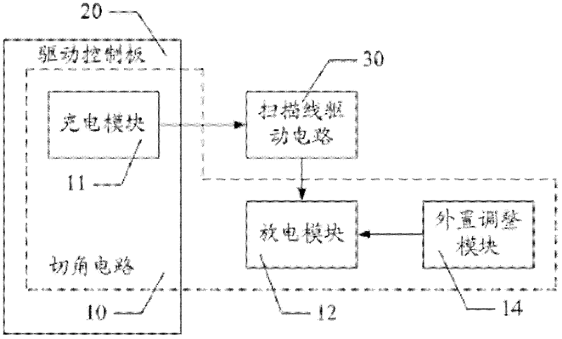
[0037] Such as figure 1 As shown, the corner cutting circuit 10 in the LCD driving system mentioned in the embodiment of the present invention is connected to a plurality of scanning line driving circuits 30, including:

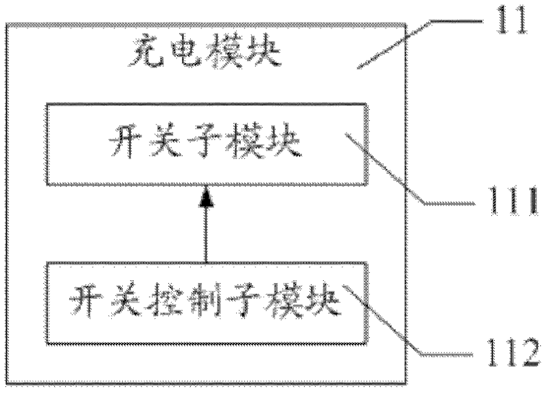
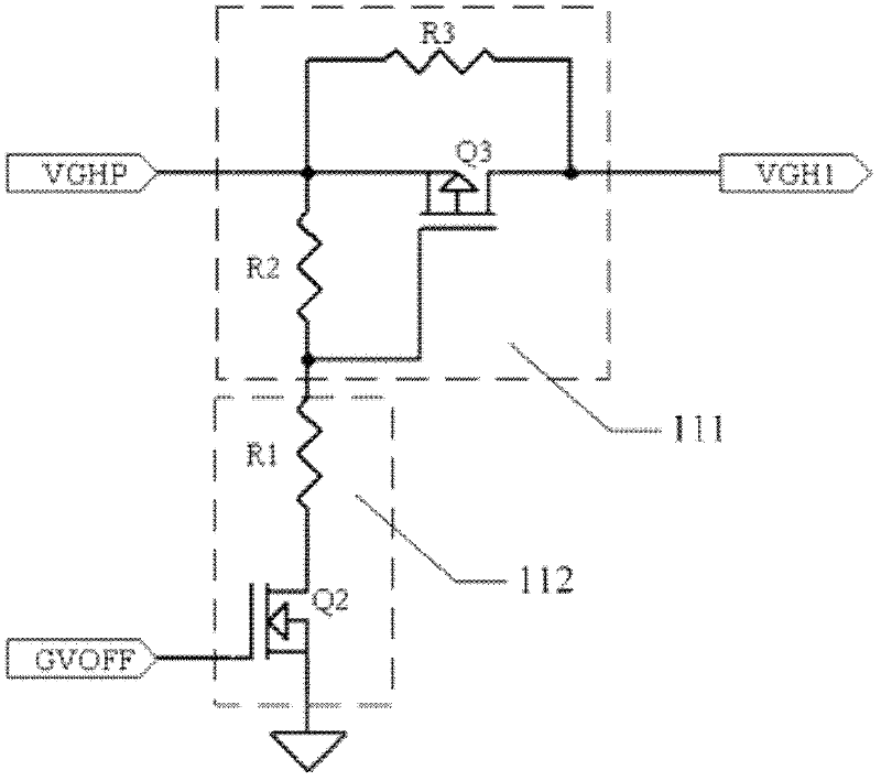
[0038] The charging module 11 is integrated on the control board 20, accepts the input of the DC driving voltage, and outputs the turn-on voltage to charge the scanning line driving circuit 30;

[0039] A plurality of discharge modules 12 are respectively integrated on each scanning line driving circuit 30 to control the corresponding scanning line driving circuit 30 to discharge.

[0040] A plurality of external adjustment modules 14 are externally connected to each scan line driving circuit 30 and connected to the corresponding discharge module 12 for adjusting the discharge module 12 to control t...


PUM


Abstract

The invention discloses a corner-cutting circuit in an LCD (Liquid Crystal Display) driving system, which is connected with a plurality of scanning-line driving circuits and comprises a charging circuit, a plurality of discharging modules and a plurality of external adjusting modules, wherein the charging circuit is integrated on a control plate and is used for receiving the input of a direct-current driving voltage and outputting an opening voltage for charging the scanning-line driving circuits; the discharging modules are respectively integrated on each scanning-line driving circuit and are used for controlling the corresponding scanning-line driving circuit to be discharged; and the external adjusting modules are respectively and externally connected to the external part of each scanning-line driving circuit, are connected with the corresponding discharging modules and are used for adjusting the discharging modules to control the discharging speeds of the scanning-line driving circuits. In the invention, the size of a variable resistor which is externally connected onto a discharging resistor is regulated according to the size of the respective parasitic capacitor of each scanning-line driving circuit to further adjust the discharging slope of the corresponding scanning-line driving circuit, so that the corner-cutting circuit is applicable to the scanning-line driving circuits with different parasitic capacitors.

Description

technical field [0001] The invention relates to the field of LCD driving, in particular to a corner cutting circuit in the LCD driving system. Background technique [0002] In the LCD driving architecture, in order to reduce the feedback voltage and linear variation effect, it is necessary to add a corner cutting circuit to the LCD driving system, and adjust the slope of the driving voltage waveform through the corner cutting circuit, that is, generate corner cutting. At present, the corner cutting circuit has been widely used in every model. Usually, each component of the corner cutting circuit is installed on the control board of the LCD drive system, and the MOS tube is used as the switch component to control the turn-on voltage to charge the scanning line drive circuit. At the same time, the discharge module is connected in parallel to the output terminal of the discharge voltage of the scan line drive circuit. When the control signal controls the MOS transistor to be tu...

Claims


Application Information

Patent Timeline
Patent Type & Authority Applications(China)
IPC IPC(8): G09G3/36
CPCG09G5/00G09G3/36G09G3/3677G09G3/3696G09G2330/045
Inventor 林柏伸谭小平陈明暐
Owner TCL CHINA STAR OPTOELECTRONICS TECH CO LTD
Why Eureka
Try Eureka