
A laser pipe cutting machine

A tube cutting machine and laser cutting technology, applied in laser welding equipment, metal processing equipment, welding equipment and other directions, can solve the problem of inability to take out small sections of pipes in sections, and achieve the goal of improving the quality rate, avoiding crowding, and improving working hours. Effect

Active Publication Date: 2021-11-09
济南鼎点数控设备有限公司
View PDF0 Cites 0 Cited by
  • Summary
  • Abstract
  • Description
  • Claims
  • Application Information

AI Technical Summary

Problems solved by technology

[0003] In the existing laser cutting pipe operation, the cut small pipes are accumulated on the laser pipe cutting machine as the number increases. With the increase in the number of small pipes, and during the working process, the operator cannot be distracted to segment the small pipes take out

Method used


Image

  • A laser pipe cutting machine
  • A laser pipe cutting machine
  • A laser pipe cutting machine

Examples


Embodiment 1

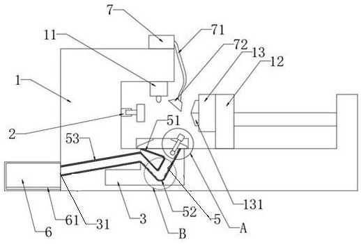
[0036] Embodiment one, with reference to figure 1 As shown, a laser pipe cutting machine includes a device body 1, a push plate 2 is fixed on one side of the inner wall of the working space of the device body 1, and a laser cutting part 11 is fixed on the top of the inner wall of the working space. The laser cutting part 11 is a working part. A fixed plate 12 is fixed on the bottom of the inner wall of the working space, and a fixed block 13 is arranged on the side of the fixed plate 12 close to the push plate 2 , and a chuck 131 is arranged on the fixed block 13 . The chuck 131 is facing the platen 2 . One side of the device body 1 is provided with a cooling oil placement groove 3 , and cooling oil is placed inside the cooling oil placement groove 3 . When the small section of pipe enters the inside of the cooling oil placement groove 3, due to the effect of the cooling oil, the small section of pipe will not directly contact with the cooling oil placement groove 3, so as t...

Embodiment 2

[0045] Embodiment two: refer to Figure 2-Figure 3 As shown, the difference between embodiment two and embodiment one is:

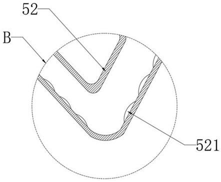
[0046] One side of the inner wall of the V-shaped tube 52 is provided with a plurality of clamping pads 521 equidistantly along its own shape;

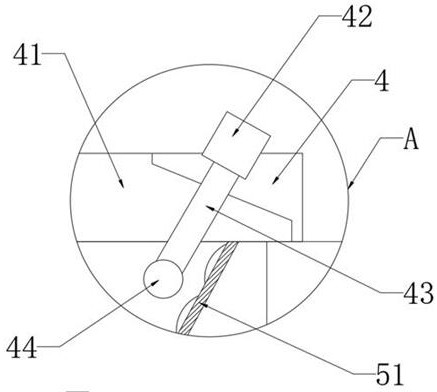
[0047] The top of the splash-proof block 4 is provided with a telescopic part 42, the moving end of the telescopic part 42 is fixed with a connecting rod 43, and the other end of the connecting rod 43 is fixed with a push block 44; parallel.

[0048] The specific implementation process,

[0049] In actual work, the cut small section of pipe falls into the inside of the tapered through hole 41 inside the splash block 4 , and the small section of pipe falls from the tapered through hole 41 into the horn through pipe 51 . At this moment, the small section pipe is submerged in the cooling oil in the cooling oil placement groove 3 inside.

[0050] Due to its own gravity, the small section of pipe enters the V-shap...


PUM


Abstract

The present invention relates to the technical field of laser pipe cutting machines, in particular to a laser pipe cutting machine, which includes a device body, a push plate is fixed on one side of the inner wall of the working space of the device body, and a laser cutting part is fixed on the top of the inner wall of the working space. The bottom of the inner wall of the working space is fixed with a fixed plate, and the side of the fixed plate close to the pushing plate is provided with a fixed block, the fixed block is provided with a chuck, and the side of the device body is provided with cooling oil The vertical section of the cooling tank placement tank is L-shaped, and a first through hole is opened on one side of the placement body, and the first through hole communicates with the inside of the cooling oil placement tank. The invention has the effect of realizing the purpose of collecting while cutting, and can separate small tubes of different materials, so as to avoid the phenomenon that the small tubes of different materials are intermixed with each other.

Description

technical field [0001] The invention relates to the technical field of laser pipe cutting machines, in particular to a laser pipe cutting machine. Background technique [0002] The laser pipe cutting machine uses a laser to cut the long pipe into sections, and can draw on the outer peripheral surface of the long pipe. [0003] In the existing laser cutting pipe operation, the cut small pipes are accumulated on the laser pipe cutting machine as the number increases. With the increase in the number of small pipes, and during the working process, the operator cannot be distracted to segment the small pipes take out. Especially when corresponding to small pieces of tubes of different types and materials, the operator needs to pause the machine before taking out the small pieces of tubes that have been cut before. It takes a certain amount of time to take out the small tubes at this time (the operator must stop the machine so that the small tubes can be taken out under certain ...

Claims


Application Information

Patent Timeline
Patent Type & Authority Patents(China)
IPC IPC(8): B23K26/38B23K26/70B23K26/02
CPCB23K26/02B23K26/38B23K26/702
Inventor 于银
Owner 济南鼎点数控设备有限公司
Learn More