
Power source device

A technology of a power supply device and a forward converter, which is applied to emergency protection circuit devices, electrical components, conversion equipment for intermediate conversion to DC conversion, etc., can solve the problems of device output stop and reduced operation reliability.

Active Publication Date: 2014-04-23
FUJI ELECTRIC CO LTD
View PDF5 Cites 0 Cited by
  • Summary
  • Abstract
  • Description
  • Claims
  • Application Information

AI Technical Summary

Problems solved by technology

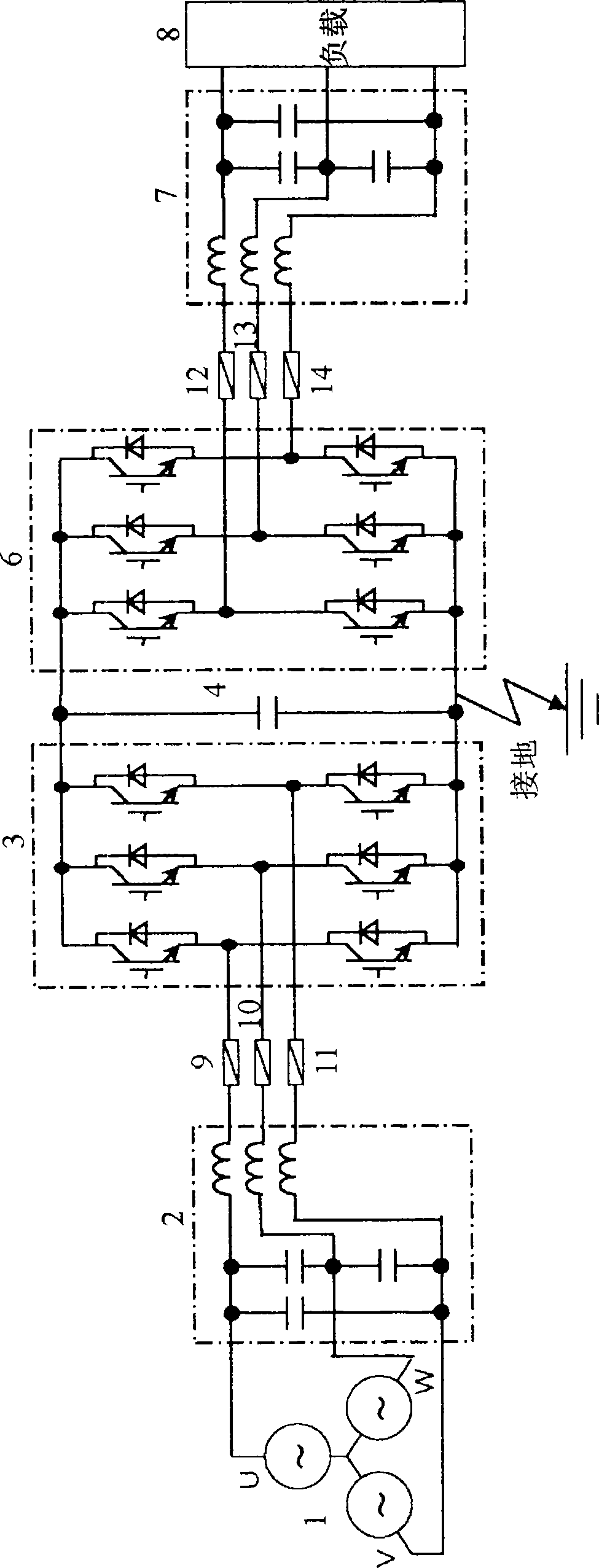
in composition figure 1 On the basis of the power supply device in the power supply device, when the fuses 9 to 14 for protection are blown due to the failure or loss of the fuse itself, the output of the device will be stopped, and the operation reliability will be reduced. The fuse for electric power is required to protect semiconductor elements It is desirable to use as few high-speed cut-off fuses as possible due to their high price and large size.

Method used


Image

  • Power source device
  • Power source device
  • Power source device

Examples


Embodiment 1

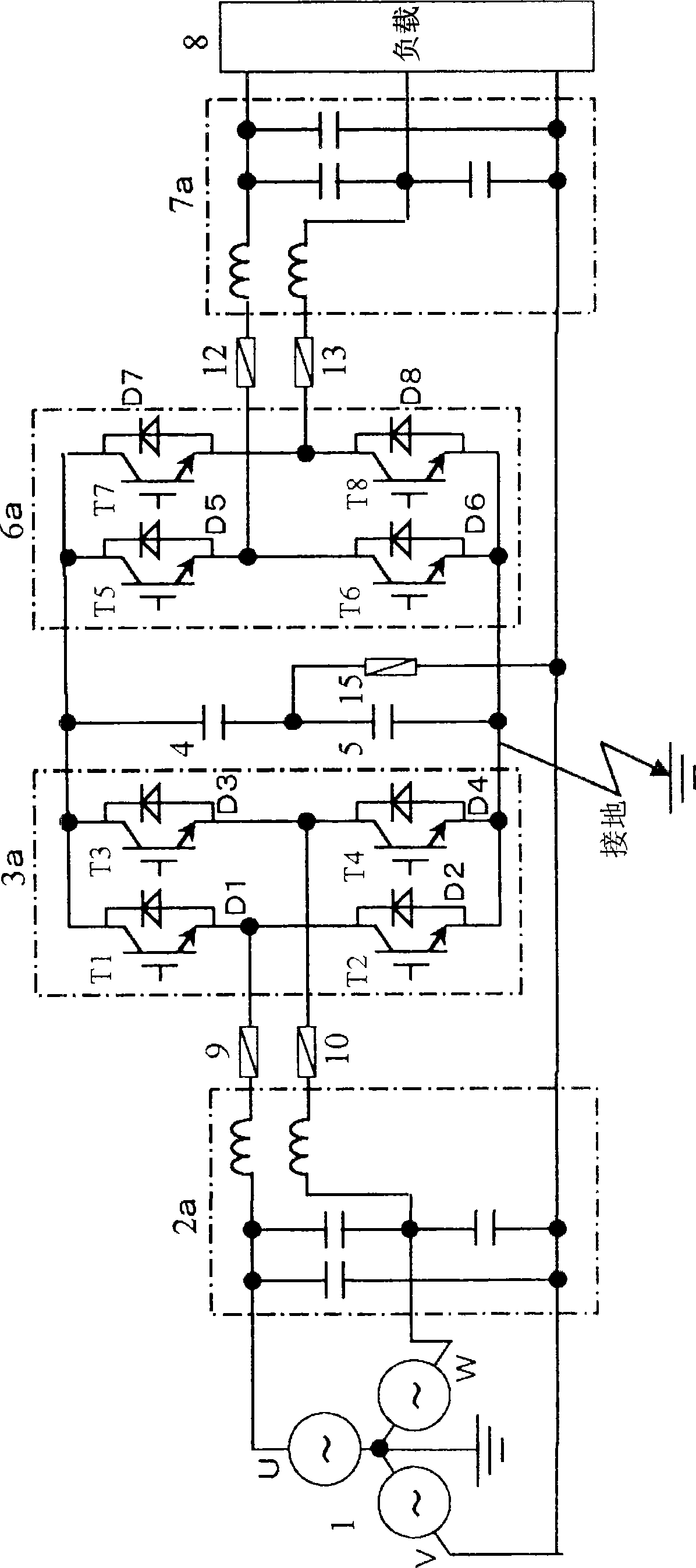
[0018] figure 2 shows the first embodiment of the present invention. The AC input of the forward converter 3a composed of IGBTT1-T4 and diodes D1-D4 is connected to the AC input filter 2a via fuses 9 and 10, and the input of the AC input filter 2a is connected to each of the three-phase AC power supply 1 respectively. connected. In addition, the output of inverter 6a composed of IGBT5-T8 and diodes D5-D8 is connected to AC output filter 7a via fuses 12 and 13, and the output of AC output filter 7a is connected to load 8, respectively. A series circuit of capacitors 4 and 5 is connected between the DC terminals of the forward converter 3a and the reverse converter 6a (between the positive pole and the negative pole), and the series connection point (neutral pole) of the capacitors 4 and 5 is connected to the 3-phase AC power supply The V-phase of 1 and the 1-phase of the load are connected via a fuse 15 .

[0019] The protection operation in such a structure will be describ...

Embodiment 2

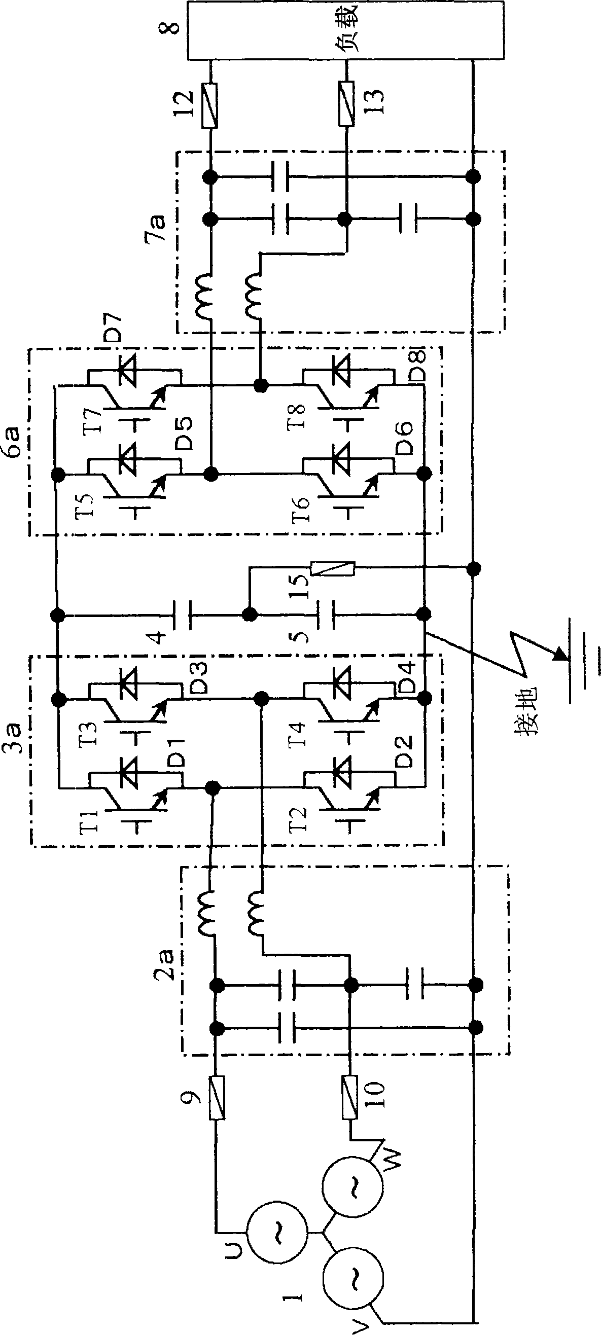
[0024] exist image 3 shows the second embodiment of the present invention. The difference from the first embodiment is the insertion positions of the fuses 9, 10 between the AC power source 1 and the forward converter 3a, and the fuses 12, 13 between the reverse converter 6a and the load 8. In Embodiment 1, fuses 9 and 10 are inserted between the AC input of the forward converter 3a and the AC input filter 2a on the side of the AC power supply 1, but in the second embodiment, fuses 9 and 10 are inserted between the AC input of the forward converter 3a and the AC input filter 2a. Between the input filter 2a and the AC power supply 1. In addition, on the AC output side of Embodiment 1, fuses 12 and 13 are inserted between the inverter 6a and the AC output filter 7a, but in the second embodiment, fuses 12 and 13 are inserted between the AC output filter 7a and load between 8. The protection action is the same as that of the first embodiment, so it is omitted.

[0025] In add...


PUM


Abstract

The invention provides a power source device. A forward converter with a positive electrode, a neutral electrode and a negative electrode is used to convert the three-phase alternating current into the direct current, and a reverse converter is used to convert the direct current converted by the forward converter into the three-phase alternating current. The power source device comprises the forward converter, the reverse converter and a capacitor series circuit respectively connected with the positive electrode, the neutral electrode and the negative electrode of the forward converter, thereby forming the input-output non-insulated power source device. The power source device also comprises a common line, which connects a single-phase alternating current input, a single-phase alternating current output and the neutral electrode of the direct current part. The alternating current input of the forward converter is connected with two fuses, while the alternating current output of the reverse converter is connected with two fuses as well. In addition, a fuse is connected between the neutral electrode of the forward converter and the common line.

Description

technical field [0001] The invention relates to a protection circuit of a 3-phase input and output power supply device. Background technique [0002] figure 1 The circuit structure of the 3-phase input and output power supply device of the prior art is shown in . It is a circuit example of the above-mentioned 3-phase input-output power supply device as follows: the AC of the 3-phase AC power supply 1 is converted into DC by a forward converter (forward converter) 3, smoothed by a capacitor 4, and then converted by a reverse converter (inverse converter). Converter) 6 into AC and output. Fuses 9 , 10 , and 11 are respectively connected to the AC input of the forward converter 3 , and an AC input filter 2 composed of a reactor and a capacitor is connected to their AC power source 1 side. Fuses 12 , 13 , and 14 are connected to each phase of the AC output side of the flyback converter 6 , and an AC output filter 7 composed of a reactance coil and a capacitor is connected bet...

Claims


Application Information

Patent Timeline
Patent Type & Authority Patents(China)
IPC IPC(8): H02M5/44H02H7/10
Inventor 山方义彦我妻裕
Owner FUJI ELECTRIC CO LTD
Learn More