Compact pressure relief valve

A technology of overpressure valve and matrix, applied in the field of overpressure valve, can solve the problem of lack of vacuum strength and other problems

Inactive Publication Date: 2012-01-11
SYNTEGON TECHNOLOGY GMBH
View PDF8 Cites 0 Cited by
  • Summary
  • Abstract
  • Description
  • Claims
  • Application Information

AI Technical Summary

Problems solved by technology

In contrast, valves with only a small opening pressure do not have the necessary vacuum strength

Method used


Image

  • Compact pressure relief valve
  • Compact pressure relief valve
  • Compact pressure relief valve

Examples


Embodiment Construction

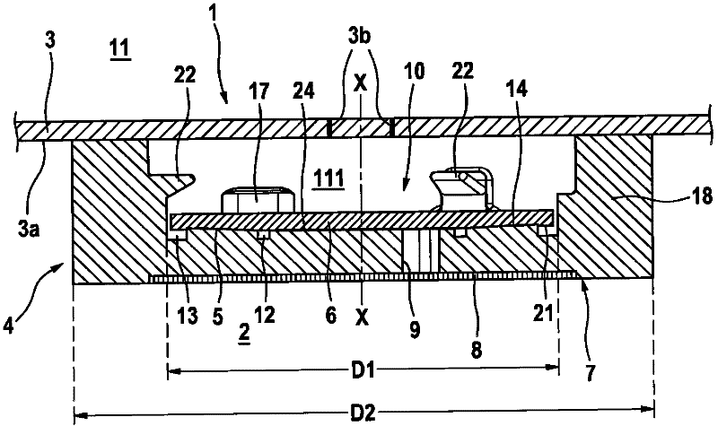
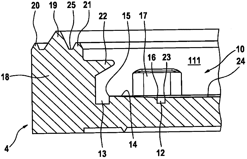
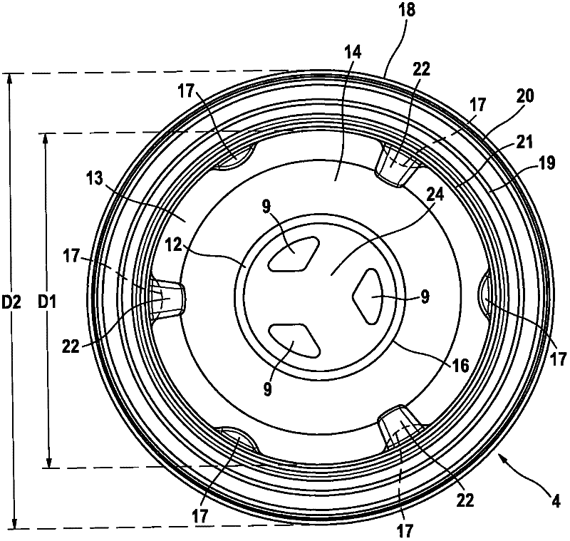
[0021] Refer below Figures 1 to 3 The pressure relief valve 1 according to a first preferred embodiment of the invention will be described in detail.

[0022] as by figure 1 It can be seen that the pressure relief valve 1 according to the invention comprises a base body 4 and a diaphragm 6 . The pressure relief valve 1 is fastened to the inner side 3 a of the packaging 3 by means of an encapsulation process. Openings 3b are provided in the packaging 3, below which openings the pressure relief valve 1 is fixed. exist figure 1 In , the inner space of the package 3 is marked with the reference number 2 , while the outer space (surrounding environment) of the package is marked with the reference number 11 . The pressure relief valve 1 here has the task of venting an excess pressure that may arise in the packaging 3 to the outside 11 and sealing a vacuum that may be present in the packaging 3 from the outside.

[0023] The base body 4 is cylindrical or slightly conical and ha...


PUM


Abstract

The invention relates to a pressure relief valve for a packaging container (3), comprising a base body (4) with at least one through opening (9, 29), a sealing surface (14) and a peripheral region (18), wherein the peripheral region (18) may be sealably connected to an inner surface (3a) of the packaging container (3), the sealing surface (14) having an inwardly tapering form and a flexible membrane (6), in contact with the sealing surface (14) of the base body (4) to generate a sealing effect. The membrane (6) covers the through opening (9), a fluid (5) is arranged between the sealing surface (14) and the membrane (6), wherein a recess (10) is formed in the base body (4) to accommodate thee membrane (6). The recess (10) has a first diameter (D1), between 70 and 80% of a total diameter (D2) of the base body (4).

Description

technical field [0001] The invention relates to a pressure relief valve for packaging containers, which pressure relief valve has small dimensions. Background technique [0002] Pressure relief valves for packaging containers are known in various designs from the prior art. The use of valves, especially on flexible packaging for food products, has been achieved through various technical solutions. The main requirement for such valves is that they allow only small overpressures in the packaging by corresponding opening and otherwise reliably prevent the ingress of ambient air. Here, the ingress of ambient air must be prevented even at very low pressures within the packaging. In practice, however, the two above-mentioned objectives are opposed to each other, since on the one hand there should be only a small opening pressure to open the valve, while on the other hand a high vacuum strength should be provided. Therefore, a valve with a high vacuum strength also has a high op...

Claims


Application Information

Patent Timeline
Patent Type & Authority Applications(China)
IPC IPC(8): B65D77/22F16K99/00
CPCF16K99/0001B65D77/225F16K17/18F16K15/141Y10T137/7879
Inventor H-P·施塔德尔H·施托特基维茨J·哈克
Owner SYNTEGON TECHNOLOGY GMBH
Why Eureka
Try Eureka