Antenna lifting device and electromagnetic wave measuring system

A lifter and lifting mechanism technology, which is applied to antennas, measuring devices, measuring electrical variables, etc., can solve the problems of inability to measure the measured instruments with different heights, insufficient adjustment, etc.

Inactive Publication Date: 2012-01-11
TOKIN CORP
View PDF10 Cites 12 Cited by
  • Summary
  • Abstract
  • Description
  • Claims
  • Application Information

AI Technical Summary

Problems solved by technology

[0008] However, in the measurement system of Patent Document 4, since only certain elevation angles can be adjusted, there are cases where the adjustment is insufficient
In addition, in the measurement system of Patent Document 4, since it is impossible to measure instruments with greatly different heights, it is necessary to prepare a measurement system for each instrument to be measured.

Method used


Image

  • Antenna lifting device and electromagnetic wave measuring system
  • Antenna lifting device and electromagnetic wave measuring system
  • Antenna lifting device and electromagnetic wave measuring system

Examples


Embodiment Construction

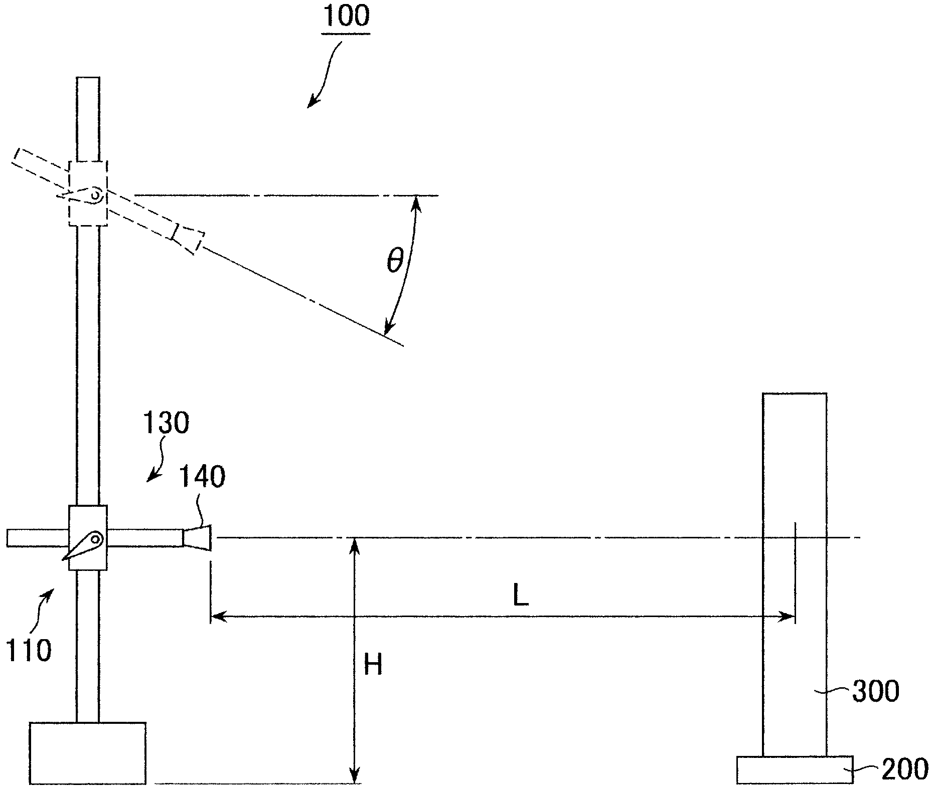
[0053] refer to figure 1 , The electromagnetic wave measurement system according to the embodiment of the present invention includes an antenna lifter 100 and a turntable 200 disposed separately from the antenna lifter 100 . An instrument under test (EUT) 300 is mounted on the turntable 200 .

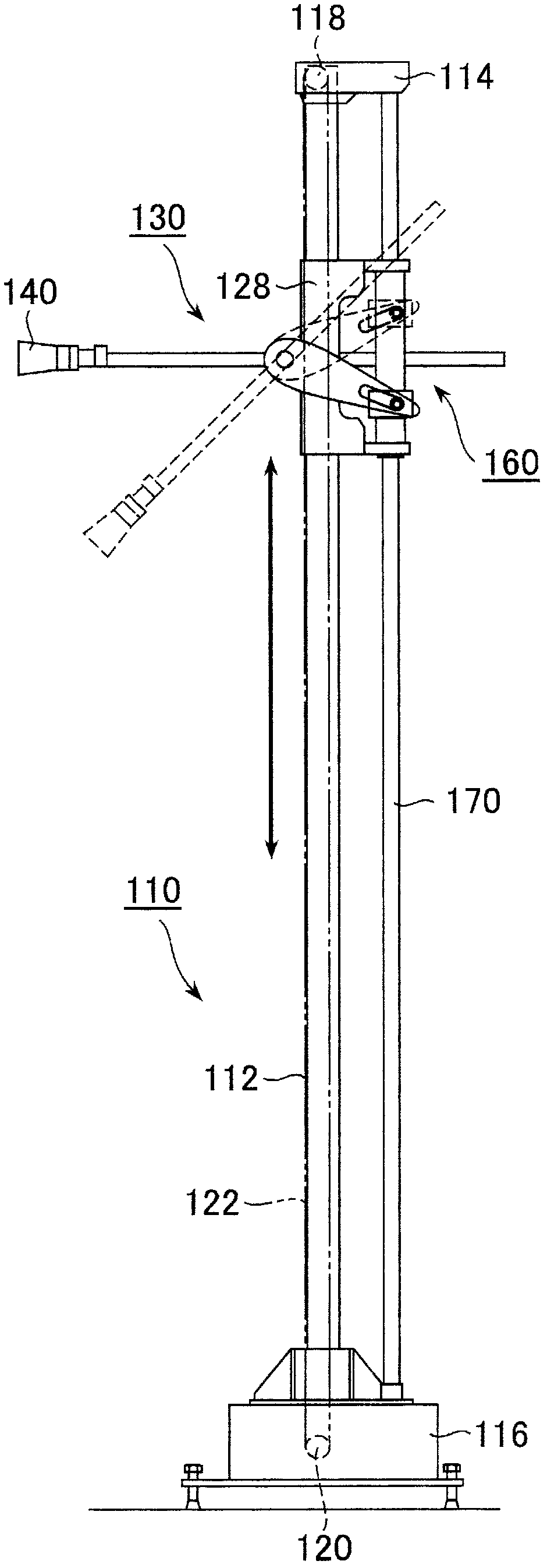
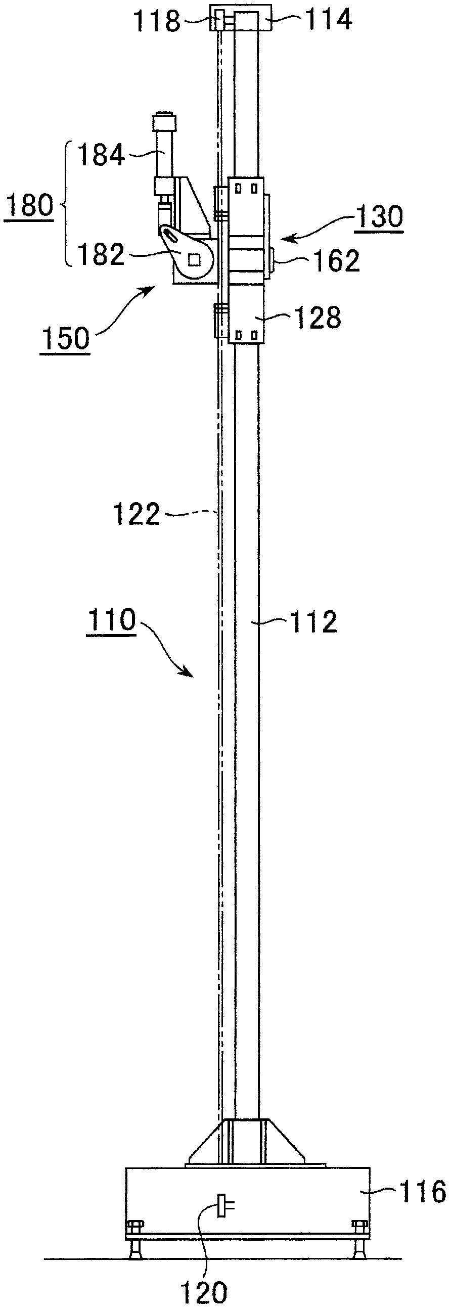
[0054] Such as figure 2 as well as image 3 As shown, the antenna lifter 100 includes an antenna unit 130 and a lifting mechanism 110 for vertically lifting the antenna unit 130 .

[0055] Such as figure 2 as well as image 3 As shown, the lifting mechanism 110 includes: an antenna rod 112 extending in the vertical direction; and an upper member 114 and a lower member 116 connected by the antenna rod 112 . An upper pulley 118 is provided on the upper member 114 , and a lower pulley 120 is provided on the lower member 116 . A belt 122 is stretched over the upper pulley 118 and the lower pulley 120 . Such as Figure 4 As shown, the lower pulley 120 is connected to a motor 126 vi...


PUM


Abstract

An antenna lifting device is provided with an antenna unit and a lifting mechanism which brings up / down the antenna unit in the vertical direction. The antenna unit is provided with an antenna, an antenna supporting mechanism which supports the antenna, and an elevation angle adjusting mechanism configured to adjust the elevation angle of the antenna. The elevation angle adjusting mechanism adjusts the elevation angle of the antenna by rotating the antenna supporting mechanism, and the elevation angle can be adjusted independently from operation of bringing up / down the antenna unit by the lifting mechanism. Since the elevation angle of the antenna can be discretionary adjusted, electromagnetic wave measurement can be performed more accurately.

Description

technical field [0001] The invention relates to an antenna lifter and an electromagnetic wave measuring system equipped with the antenna lifter. Background technique [0002] In order to evaluate the electromagnetic interference wave of the electronic device, the measurement of the electromagnetic wave emitted from the electronic device is performed. The measurement is performed in an anechoic chamber or open sight. As an apparatus or system used for electromagnetic wave measurement, there are techniques disclosed in Patent Documents 1 to 3, for example. However, the devices and systems disclosed in Patent Documents 1 to 3 have a problem that the elevation angle of the antenna cannot be adjusted. [0003] In contrast, the device disclosed in Patent Document 4 includes a mechanism for automatically adjusting the elevation angle of the antenna in accordance with the vertical position of the antenna. [0004] Patent Document 1: Japanese Patent Laid-Open No. 2007-033254 [0...

Claims


Application Information

Patent Timeline
Patent Type & Authority Applications(China)
IPC IPC(8): G01R29/10H01Q3/02
CPCH01Q3/02G01R29/0871G01R29/10H01Q1/12
Inventor 铃木贤弥佐藤敏胜
Owner TOKIN CORP
Why Eureka
Try Eureka