Techniques for angle resolution in radar

a technology of angle resolution and radar, applied in the field of radars, can solve the problems of time-consuming process of detecting obstacles using ultrasonic sensors, risks associated with drilling and mounting transducers into the bumper,

Active Publication Date: 2015-07-02
TEXAS INSTR INC
View PDF9 Cites 51 Cited by
  • Summary
  • Abstract
  • Description
  • Claims
  • Application Information

AI Technical Summary

Problems solved by technology

A vehicle generally requires multiple parking sensors to cover the entire rear of the vehicle which makes it a cost intensive solution.
Thus, the process of detecting obstacles using ultrasonic sensors is time consuming which is unsafe in vehicles moving with high velocity.
There are risks associated with drilling and mounting the transducers into the bumper.
The performance of ultrasonic sensors is severely degraded when the sensors are covered with snow.
In addition, the range over which the ultrasonic sensors operates is limited.
In addition, sensitivity of a pulse radar is directly proportional to the power which complicates the design process of the pulse radar.
As FMCW radars are used in a broad range of applications, their design becomes more cost-sensitive.

Method used


Image

  • Techniques for angle resolution in radar
  • Techniques for angle resolution in radar
  • Techniques for angle resolution in radar

Examples


Embodiment Construction

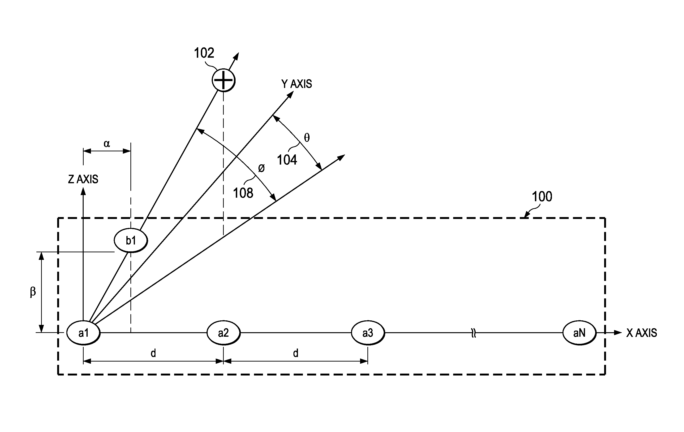
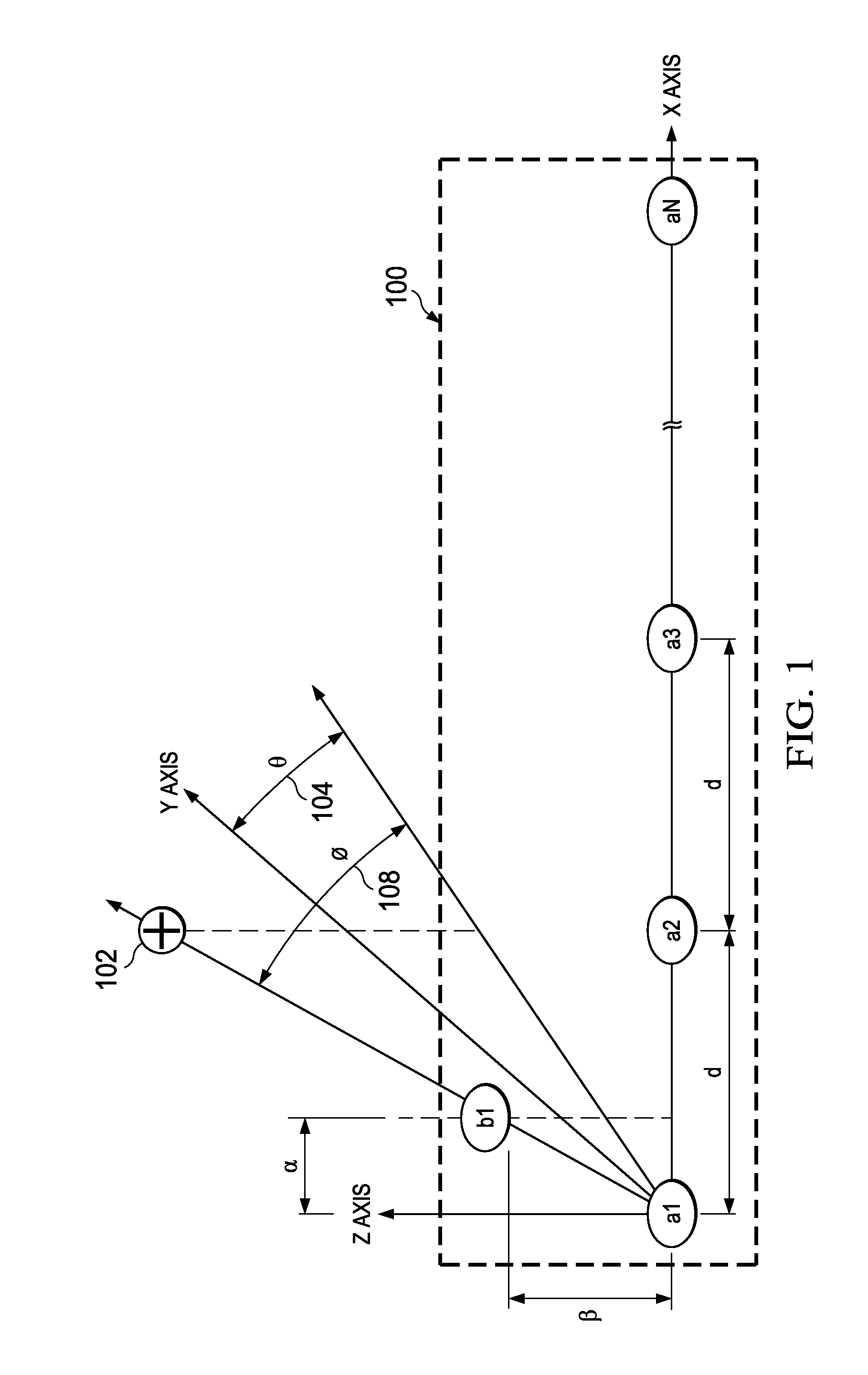
[0021]FIG. 1 illustrates a receive antenna unit 100 in a radar apparatus, according to an embodiment. In an embodiment, the receive antenna unit 100 is integrated in a radar apparatus which is further integrated in an industrial or automotive application. The receive antenna unit 100 includes a linear array of antennas. The linear array of antennas includes a plurality of antennas, for example, antenna a1, a2, a3 and aN, where aN is the Nth antenna and N is an integer. For the sake of simplicity and understanding, the plurality of antennas represented in FIG. 1 will be represented as a1-aN further in the description. The linear array of antennas a1-aN is represented to be placed along the X-axis. The adjacent antennas in the linear array of antennas a1-aN are separated by a spacing d i.e. the antennas a1 and a2 are placed at distance from each other.

[0022]The receive antenna unit 100 further includes an additional antenna b1. The additional antenna b1 is at a predefined offset from ...


PUM


Abstract

A radar apparatus for estimating position of a plurality of obstacles. The radar apparatus includes a receive antenna unit. The receive antenna unit includes a linear array of antennas and an additional antenna at a predefined offset from at least one antenna in the linear array of antennas. The radar apparatus also includes a signal processing unit. The signal processing unit estimates an azimuth frequency associated with each obstacle of the plurality of obstacles from a signal received from the plurality of obstacles at the linear array of antennas. In addition, the signal processing unit estimates an azimuth angle and an elevation angle associated with each obstacle from the estimated azimuth frequency associated with each obstacle.

Description

CROSS REFERENCES TO RELATED APPLICATIONS[0001]This application claims priority from India provisional patent application No. 4825 / CHE / 2013 filed on Oct. 25, 2013, which is hereby incorporated by reference in its entirety.TECHNICAL FIELD[0002]Embodiments of the disclosure relate generally to radars.BACKGROUND[0003]A vehicle has parking sensors to detect an obstacle behind the vehicle. The parking sensors determine a distance of the vehicle from the obstacle using ultrasonic signals when backing a vehicle. The parking sensor operates at ultrasonic frequencies. The parking sensor outputs an ultrasonic detecting signal to detect whether any obstacle is behind the rear of the vehicle and receives an ultrasonic signal as reply from the obstacle. A vehicle generally requires multiple parking sensors to cover the entire rear of the vehicle which makes it a cost intensive solution. Also, the ultrasonic parking sensors use a time division obstacle detecting method in which each sensor sends a...

Claims


Application Information

Patent Timeline
Patent Type & Authority Applications(United States)
IPC IPC(8): G01S13/06G01S13/931
CPCG01S13/06G01S7/354G01S13/34G01S13/42G01S13/931H01Q3/2629H01Q1/3233H01Q3/247H01Q21/08G01S7/032
Inventor RAO, SANDEEPKHANNA, SAURABH
Owner TEXAS INSTR INC
Why Eureka
Try Eureka