Eureka AIR delivers breakthrough ideas for toughest innovation challenges, trusted by R&D personnel around the world.

Correction method for measuring luminous flux by using integral method

A technology of luminous flux and integral method, applied in the field of optical radiation measurement, which can solve the problem of low measurement accuracy

Active Publication Date: 2013-04-03
杭州伏达光电技术有限公司
View PDF3 Cites 0 Cited by
  • Summary
  • Abstract
  • Description
  • Claims
  • Application Information

AI Technical Summary

Problems solved by technology

Of course, LEDs with different structures have different beam angles. Generally speaking, the larger the beam angle, the higher the measurement accuracy; the smaller the beam angle, the lower the measurement accuracy

Method used


Image

  • Correction method for measuring luminous flux by using integral method
  • Correction method for measuring luminous flux by using integral method
  • Correction method for measuring luminous flux by using integral method

Examples


Embodiment 1

[0034] Embodiment 1: a kind of correction method of integral method measuring luminous flux, comprises the following steps:

[0035] a) First, calculate the luminous flux correction coefficient K through the following formula (1):

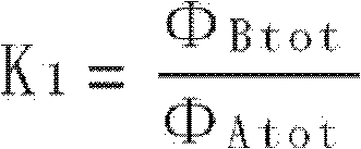
[0036] K = K 1 × Σ zone = 1 n ( Φ Azone × F zone ) Σ zone = 1 n ( Φ Bzone × F z...

Embodiment 2

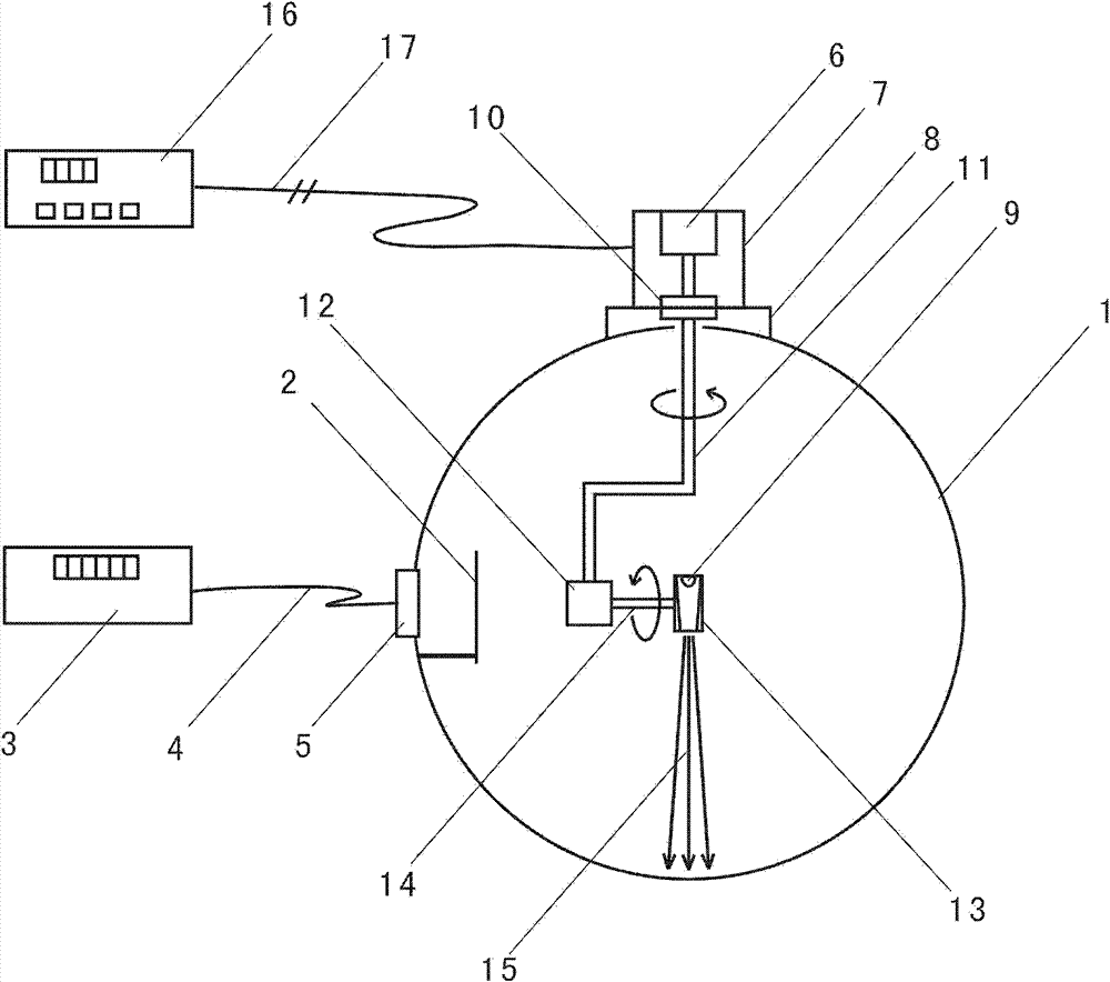
[0061] Embodiment 2: refer to figure 1 . A device for measuring relative reflection distribution parameters at various angles of an integrating sphere. Two holes are opened on the integrating sphere 1 to be measured: one hole is used to install the illuminance probe 5; 11 is slightly larger in diameter. The illuminance probe 5 calibrated by V(λ) is located on the wall of the integrating sphere behind the shading baffle 2 belonging to the attachment of the integrating sphere to be measured, and the signal of the illuminance probe 5 is transmitted to the display instrument 3 through the signal line 4 . The motor 6 is fixed on the case 7 , the case 7 is fixed on the interface seat 8 , the interface seat 8 is fixed on the integrating sphere 1 , and the bearing 10 is fixed on the interface seat 8 . The rotating shaft 11 is connected with the motor 6 through the bearing 10 , so that the power of the motor 6 is transmitted to the rotating shaft 11 . The rotating shaft 11 with cert...

Embodiment 3

[0067] Embodiment 3: on the basis of embodiment 2, we can measure and obtain following three groups of data, are respectively: the relative light intensity distribution I of luminous flux standard lamp A (C, γ), the relative light intensity distribution I of the light source to be measured B (C, γ), the relative reflection distribution parameter E(C, γ) of each angle of the integrating sphere. Through the above three sets of data, the correction coefficient K can be calculated, and the luminous flux measured by the integration method of the measured light source can be corrected by the correction coefficient K, as follows:

[0068] 1) According to the total luminous flux calculation formula of C-γ system, there are:

[0069] Φ Atot = ∫ 0 2 π ∫ 0 π I A ( ...


PUM


Abstract

The invention relates to a correction method for measuring the luminous flux by using an integral method. A luminous flux correction factor K is acquired through calculation, and the luminous flux of a measured light source, which is measured through the integral method, is corrected through the correction factor K. The advantages are that through the correction method combining the advantages ofthe distributed photometry and the integral method, the influence caused by anisotropism of an integrating sphere can be basically eliminated, so light of a light source at any light beam angle can be ripped into the anisotropic integrating sphere in any direction, and measuring results of the luminous flux basically stay the same, so the measuring accuracy is greatly improved.

Description

technical field [0001] The invention relates to the field of optical radiation measurement, in particular to a correction method for measuring luminous flux by an integral method. Background technique [0002] In the field of optical radiation measurement, luminous flux is one of the most important basic parameters for describing light sources. There are usually two methods for measuring the luminous flux of a light source, namely the distribution photometry method and the integral method. Spectrophotometry has high measurement accuracy in theory, but it requires high equipment and site requirements, is expensive, complicated to operate, and takes a long time to measure. Affected by factors such as work stability, the actual measurement accuracy is not high. The integration method requires relatively simple equipment, small footprint, simple operation, and quick measurement, so it is widely used. [0003] The integral method to measure luminous flux usually consists of an...

Claims


Application Information

Patent Timeline
Patent Type & Authority Patents(China)
IPC IPC(8): G01J1/00
Inventor 杨利民
Owner 杭州伏达光电技术有限公司
Why Eureka
Eureka Blog
Learn More