Screen flow equalization system

A screen and balanced technology, applied in the direction of production fluid, wellbore/well components, sealing/isolation, etc.

Inactive Publication Date: 2012-01-18
BAKER HUGHES INC
View PDF3 Cites 2 Cited by
  • Summary
  • Abstract
  • Description
  • Claims
  • Application Information

AI Technical Summary

Problems solved by technology

Additionally, the limited tolerances of the screen annulus between the screen and basepipe of conventional systems can limit the use of inflow control devices to produce viscous or heavy oils

Method used


Image

  • Screen flow equalization system
  • Screen flow equalization system
  • Screen flow equalization system

Examples


Embodiment Construction

[0023] Pipe joints, as used herein, include but are not limited to threaded oil tubing (OCTG) along a body portion of a continuous coiled tubing string or other tubing string. Means the body portion of a fitting of a given length, but is not limited to any one particular size, length or configuration of such fittings. Apertured members include holes or other apertures, or slots or other openings of any size, shape or configuration designed to allow fluid to pass therethrough. Some examples of inflow control devices are tortuous channels, orifices or other openings or passages designed to restrict or moderate inflow flow to one section of the body portion more favorably than another section.

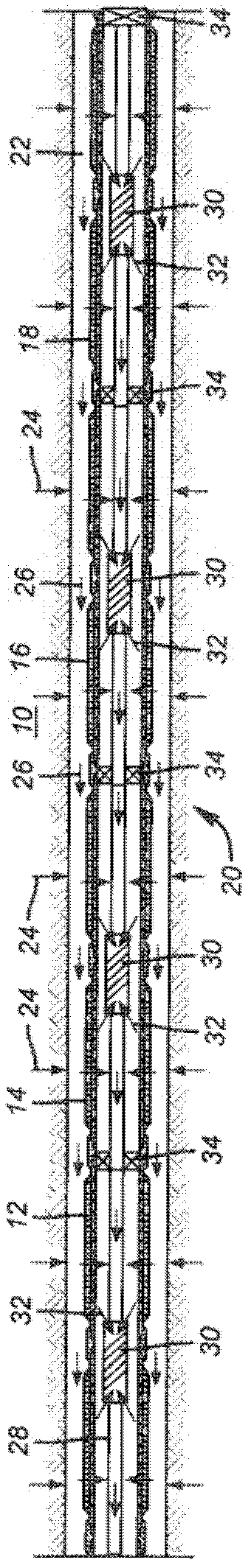
[0024] refer to figure 1Wellbore 10 , which may be an open hole or a cased hole, has a series of screen sections 12 , 14 , 16 and 18 that are connected together to form assembly 20 . Although the assembly 20 is not shown with empty pipe sections, the use of empty pipe sections still fal...


PUM


Abstract

An assembly of inflow control devices on a string along with isolation devices can be delivered into an existing or newly delivered screen assembly that requires inflow control for balanced flow from the formation. In newly delivered screen assemblies, any gravel packing that needs to be done can be accomplished without the presence of the inflow devices for faster circulation and improved gravel deposition. External annular barriers can also be delivered with an original screen assembly in a new well installation. The inflow devices and barriers can be of a variety of designs and the internal string can be removable if the barriers are retrievable to facilitate further drilling or completion below the screen assembly.

Description

[0001] Inventors: Sonny Vickery, Benn Voll, Eugene Ratterman, Eddie Bowen, and Todd Broome. technical field [0002] The technical field of the invention is the control of flow through a section of a screen, be it a newly run screen or a reconditioned screen existing in an existing wellbore, by using internal Inflow control devices are separated by inflow control devices within the screen; for new installations, an additional external annular isolator is required. Background technique [0003] Formations with long productive intervals often introduce unbalanced fluids along the interval, which can lead to water coning or other water production problems, as well as unsuitable fluids. A known solution is to balance fluid flow across long production intervals with a set of inflow control devices that can be designed to be tuned, or can be operated to divide the incoming flow into fractions and then distribute them This improves the flow characteristics of the incoming stream t...

Claims


Application Information

Patent Timeline
Patent Type & Authority Applications(China)
IPC IPC(8): E21B34/08E21B43/12
CPCE21B43/12
Inventor E·拉特曼B·A·沃尔E·G·鲍恩J·T·布鲁姆S·维克里
Owner BAKER HUGHES INC
Why Eureka
Try Eureka