Prime Mover System and Methods Utilizing Balanced Flow within Bi-Directional Power Units

a technology of bi-directional power units and prime mover systems, which is applied in the direction of machines/engines, mechanical equipment, positive displacement liquid engines, etc., can solve the problems of hydraulic lock within the prime mover, fluid moving system experiencing hydraulic lock, and unbalanced flow has been an historical issue, so as to reduce or eliminate hydraulic lock and cavitation

Active Publication Date: 2017-04-27
AOI KK
View PDF1 Cites 4 Cited by
  • Summary
  • Abstract
  • Description
  • Claims
  • Application Information

AI Technical Summary

Benefits of technology

[0020]Most specifically, in a more precise embodiment, the present invention is a prime mover system for actuating and moving one or more devices bi-directionally using at least one hydraulic and / or electrical power unit comprising one or more pumps, the pumps having at least one inlet and at least one outlet port maintaining pressure to pump fluid in either a clockwise or counterclockwise direction into and out of a pipeline such that the fluid exits the pump from either a clockwise (CW) or counterclockwise (CCW) outlet port thereby creating a clockwise or counterclockwise flow path through one or more optional fluid flow filters and through one or more valves wherein the valve(s) open and close ensuring fluid continues along the flow path with force and direction required to move the moving device(s) in a fashion determined by the user; and wherein fluid is delivered to at least one port within the moving device(s) and fluid along the flow path from the moving device(s) is blocked, redirected, or continues to flow in through the one or more additional valves due to components within the valve(s) thereby returning fluid flow from the moving device(s) thereby completing the flow path and accomplishing the ability to control intermittent or continuous movement within the moving devices.
[0021]It is critical that the system allows for fluid flow along said flow path continues flowing into and out of said pumps thereby keeping one or more motor seals and associated ports filled with fluid, thereby reducing or eliminating hydraulic lock and cavitation.

Problems solved by technology

Unbalanced flow has been an historical issue for any sealed system that is required to move fluid in either a singular or bidirectional manner.
The primary reason this problem has existed is because the fluid moving system will experience hydraulic lock when a different amount of flow going into the prime mover (such as a pump / motor) is required versus the flow that is being sent out of the prime mover.
Unfortunately, this action often creates hydraulic lock within the prime mover because common hydraulic system designs require differing volumetric amounts of fluid on the supply and return sides of an hydraulic system.
If the cross-sectional areas and resulting volumes are not exactly equal, the fluid will cause hydraulic locking of the prime mover due to the fact that the fluid is incompressible.
This eventually results in causing rapid pressures changes due to fluid flow imbalances within the hydraulic system thereby leading to hydraulic lock.

Method used


Image

  • Prime Mover System and Methods Utilizing Balanced Flow within Bi-Directional Power Units
  • Prime Mover System and Methods Utilizing Balanced Flow within Bi-Directional Power Units
  • Prime Mover System and Methods Utilizing Balanced Flow within Bi-Directional Power Units

Examples


Embodiment Construction

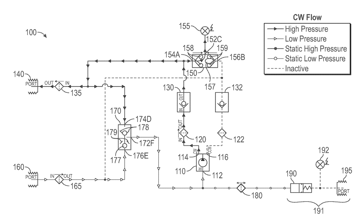
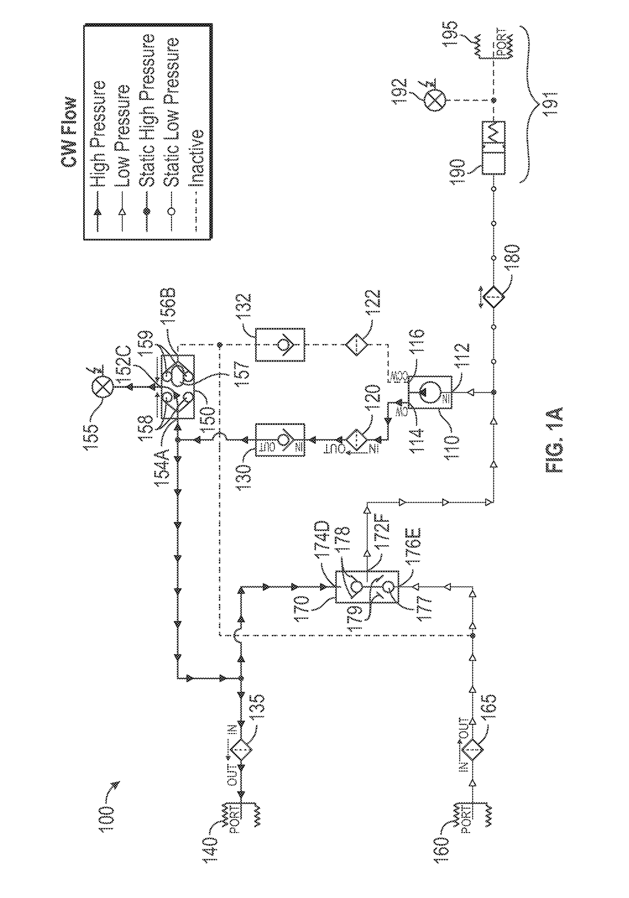
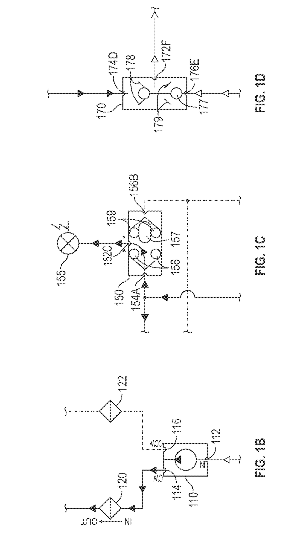
[0071]In some embodiments of the present disclosure, an actuator, such as a valve can include one or more pump systems, such as for example, one or more hydraulic pumps that can be used to move one or more fluids within the actuators. U.S. Provisional App. No. 61 / 216,942, to Ingersoll, et al., filed May 22, 2009, entitled “Compressor and / or Expander Device,” and U.S. patent application Ser. Nos. 12 / 785,086, 12 / 785,093 and 12 / 785,100, each filed May 21, 2010 and entitled “Compressor and / or Expander Device” (collectively referred to herein as the “the Compressor and / or Expander Device applications”), the disclosures of which are hereby incorporated herein by reference, in their entireties, describe various energy compression and / or expansion systems in which the systems and methods described herein can be employed.

[0072]The hydraulic actuator can be coupleable to a hydraulic pump, which can have efficient operating ranges that can vary as a function of, for example, flow rate and pres...


PUM


Abstract

Systems, methods and devices are described providing a selective hydraulic or electrically powered prime mover that is a (bi-directional power unit) PU system, including movement within a device or system used to compress and/or expand a fluid and provide fluid movement within the same device or system. The use of a (hydraulic power unit) HPU is involved and comprises at least a pump or other hydraulic fluid moving device often referred to as a “prime mover”, one or more first set of selective control valves delivering pressurized fluid to the device(s), and one or more second set of selective control valves returning unpressurized fluid from the device(s), a reservoir comprising a compensator tank, a port allowing for operation at ambient pressure, and a pressure measuring device measuring ambient pressure allowing for unbalanced flow to and from the mechanical (user) device as well as thermal expansion or compression.

Description

PRIORITY[0001]This application is a non-provisional conversion of and claims priority under 35 USC 119 from Provisional Application 62 / 245,510 filed Oct. 23, 2015 and entitled “Prime Mover System and Methods Utilizing Bi-Directional Power Units”, the entire contents of which are hereby incorporated by reference.BACKGROUND OF THE INVENTION[0002]The invention relates generally to systems and methods that include powered units (power units—PUs, and most often hydraulic power units—HPUs) designed for operating “prime movers”. These systems utilize devices that move by receiving hydraulic and / or electric power and are primarily associated with pipelines. Although the prime movers described herein in detail have been designed specifically for downhole petrochemical well applications, the assemblies and associated valve operation and engagement with actuated hydraulic cylinders and pistons pose opportunities for optimizing the actuation and efficiencies in other applications. These applica...

Claims


Application Information

Patent Timeline
Patent Type & Authority Applications(United States)
IPC IPC(8): F15B7/10F15B15/17F15B1/26
CPCF15B7/10F15B15/17F15B1/26F15B1/265F15B7/006F15B2211/20538F15B2211/20561F15B2211/27F15B2211/30505F15B2211/3052F15B2211/7052F15B2211/7053F15B2211/785F15B19/005F03C1/06F04B27/1804F04B1/12F04B49/22F04B23/021
Inventor LERNER, DANIEL MAURICEORBAN, ANDRESINGH, RANJIT
Owner AOI KK
Why Eureka
Try Eureka