
Balanced flow air conditioning system

a technology of air conditioning system and airflow, which is applied in the direction of cooling fluid circulation, vehicle heating/cooling devices, lighting and heating apparatus, etc., can solve the problems of not being able to accurately adjust the blower speed, the system cannot control the system, and the two rear passengers cannot provide consistent independent airflow volume. , to achieve the effect of simple construction

Active Publication Date: 2011-05-05
JAGUAR LAND ROVER LTD
View PDF13 Cites 3 Cited by
  • Summary
  • Abstract
  • Description
  • Claims
  • Application Information

AI Technical Summary

Benefits of technology

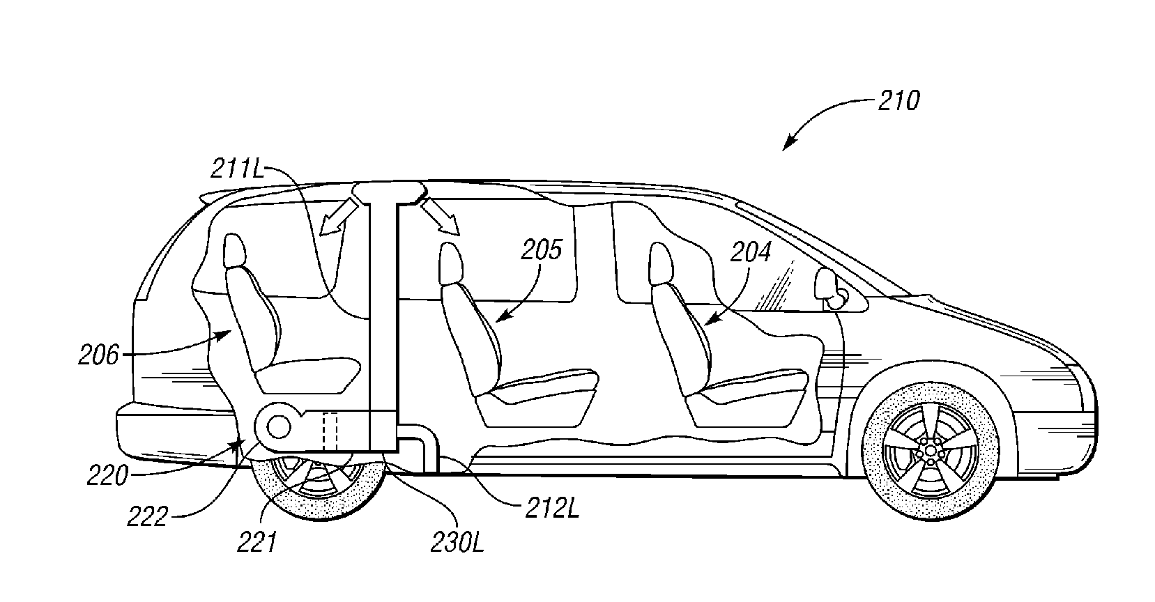
[0007]It is an object of the invention to provide an air conditioning system that is simple in construction and can supply air to two distribution conduits in a manner that enables the flow through one distribution conduit to be adjusted without significantly affecting the flow from the other distribution conduit.
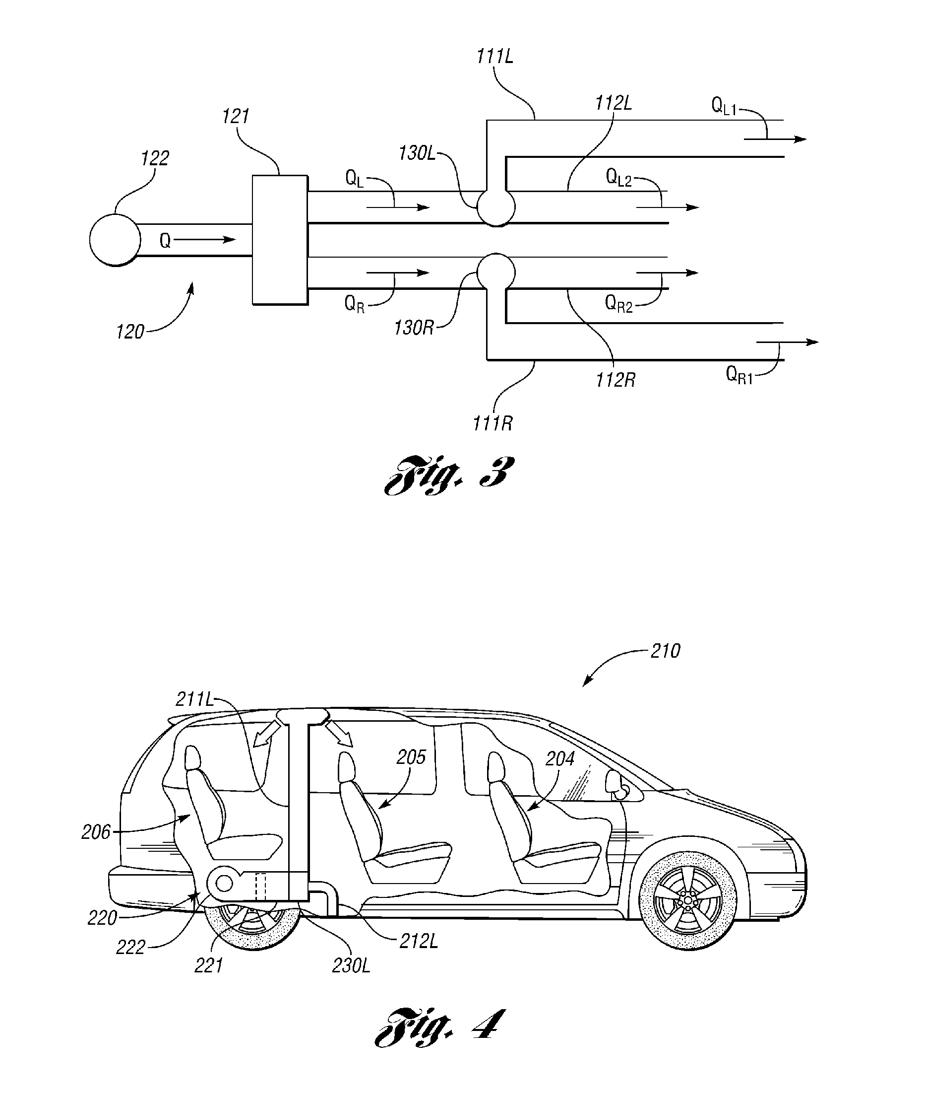
[0014]According to a third aspect of the invention there is provided a method for varying the supply of air from one of a pair of distribution conduits connected to a single blower of an air conditioning unit without affecting the flow from the other distribution conduit wherein the method comprises providing each distribution conduit with a distribution valve to alter the proportion of flow through the respective distribution conduit and a dump conduit having the same resistance to flow as the respective distribution conduit to which it is connected via the respective distribution valve and one of increasing the flow through the dump conduit to decrease the flow through the distribution conduit and decreasing the flow through the dump conduit to increase the flow through the distribution conduit.

Problems solved by technology

It is a problem with such a system that it is not possible to provide consistent independent airflow volume to the two rear occupants.
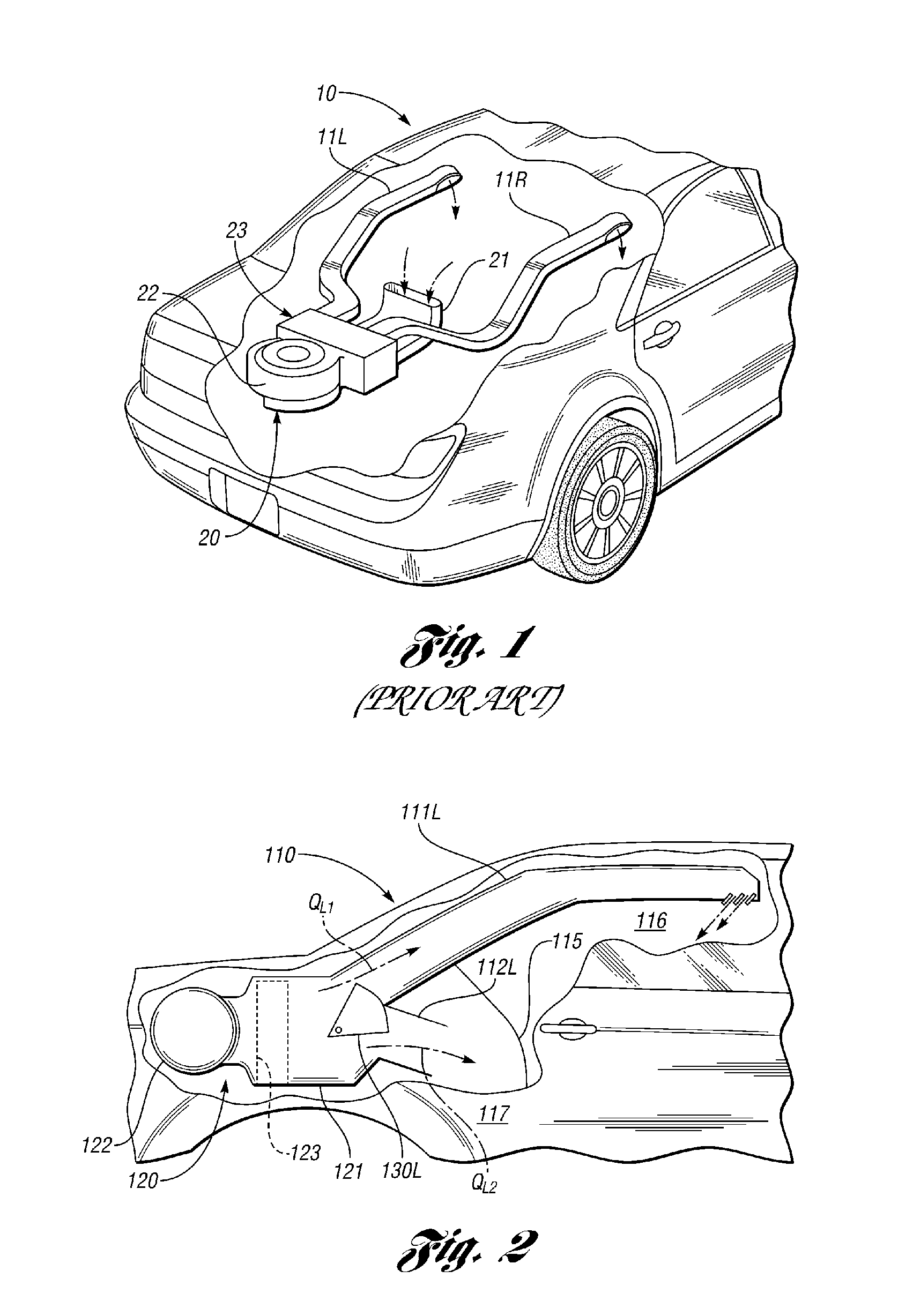
If the flow from one of the two distribution conduits 11L, 11R is turned off or the airflow is reduced then the airflow volume from the other distribution conduit 11R, 11L will increase unless the blower speed is reduced and this causes a control problem for the system because unless the flow rate through the distribution conduits 11L, 11R is constantly measured and an electronic control system is used there is no way of accurately adjusting the blower speed to return the flow through the unadjusted distribution conduit 11L or 11R to its previous level.
One solution to this problem is to separate the flows through the two distribution conduits and use separate blowers for each distribution conduit 11L, 11R but this is an expensive option and requires the separate blowers to be arranged at the outlet from the distribution chamber which is inefficient or requires separate air conditioning units to be used for each distribution conduit 11L, 11R which is expensive.

Method used


Image

  • Balanced flow air conditioning system
  • Balanced flow air conditioning system
  • Balanced flow air conditioning system

Examples


Embodiment Construction

[0021]With reference to FIGS. 2 and 3 there is shown a vehicle 110 having left and right hand side distribution conduits or ducts 111L, 111R connected to a single airbox or distribution chamber 121 of an air conditioning unit 120 for supplying air to a passenger compartment 116 of the vehicle 110.

[0022]The air conditioning unit 120 also includes a single fan or blower 122 and a heat exchange unit 123 which can selectively cool the air passing through it. The air conditioning unit 120 is mounted in a separate luggage compartment 117 of the motor vehicle 110 that is separated from the passenger compartment 116 of the vehicle 110 by a bulkhead 115.

[0023]Each of the left and right hand side distribution conduits 111L and 111R is connected to the single distribution chamber 121 via a respective distribution valve 130L, 130R which in this case is formed by a quadrant valve but could be of any suitable type. A respective dump conduit 112L, 112R is connected to each of the distribution valv...


PUM


Abstract

An air conditioning system 120 for supplying air conditioned air to a passenger compartment 116 of a motor vehicle 110 is disclosed having left and right hand side distribution ducts 111L, 111R connected to a blower 122 by a common distribution chamber 121. The blower 122 is used to cause air to flow through the common distribution chamber 121 into the left and right hand side distribution ducts 111L, 111R via an air conditioning unit 123. Each of the distribution ducts 111L, 111R includes a distribution valve 130L, 130R used to vary the flow through the respective distribution duct 111L, 111R and through a dump duct 112L, 112R that exhausts air outside of a passenger compartment 116 of the motor vehicle 110. Each of the dump ducts 112L, 112R has the same resistance to flow as the respective distribution duct 111L, 111R to which it is connected. The flow from the distribution ducts 111L, 111R is adjusted by varying the proportion of air that flows through the cooperating dump duct 112L, 112R without affecting the flow from the other distribution duct 111R, 111L or requiring the blower speed to be altered. In one embodiment the dump ducts 112L, 112R exhaust air into a luggage compartment 117 of the motor vehicle 110.

Description

BACKGROUND OF THE INVENTION[0001]1. Field of the Invention[0002]This invention relates to automotive air conditioning systems and in particular to an air conditioning system having two outlets for supplying different quantities of cooling air to left hand and right hand sides of a passenger compartment of a motor vehicle.[0003]2. Background Art[0004]A prior art air conditioning system 20 for a vehicle 10 is shown in FIG. 1. The air conditioning system 20 has a single fan or blower 22 to force air received from an inlet 21 into a single distribution chamber 23. A left hand distribution conduit 11L is connected to the distribution chamber 23 for supplying air conditioned air to a passenger sat on the left hand side of the motor vehicle 10 and a right hand distribution conduit 11R is connected to the distribution chamber 23 for supplying air conditioned air to a passenger sat on the right hand side of the motor vehicle 10.[0005]It is a problem with such a system that it is not possible...

Claims


Application Information

Patent Timeline
IPC IPC(8): F25D17/06F25D17/04
CPCB60H1/00821B60H1/24B60H2001/00164B60H1/00564B60H1/00842B60H1/00064B60H2001/00192
Inventor BAKER, ROGER
Owner JAGUAR LAND ROVER LTD
Learn More