Hydraulic steering gear

A hydraulic steering gear and rotor technology, applied in hydraulic steering gear, engine seals, engine components, etc., can solve the problems of increasing resistance during steering, large steering torque of steering gear, etc., to reduce friction and preload, reduce Power steering input torque, effect outstanding effect

Inactive Publication Date: 2012-01-25
ZHENJIANG HYDRAULICS
View PDF5 Cites 12 Cited by
  • Summary
  • Abstract
  • Description
  • Claims
  • Application Information

AI Technical Summary

Problems solved by technology

As a result, the resistance during steering is further increased, causing the steering torque to be too large when the steering gear is working

Method used


Image

  • Hydraulic steering gear
  • Hydraulic steering gear
  • Hydraulic steering gear

Examples


Embodiment Construction

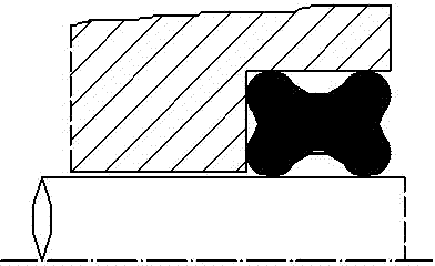
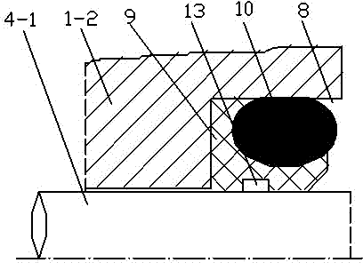
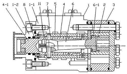
[0020] The low torque hydraulic steering gear of the present embodiment is as image 3 As shown, the housing 1-1 with the oil inlet and the oil outlet is fixedly connected with the end cover 1-2 to form the valve body 1, one end of which is fixedly connected with the stator 3 equipped with the cycloid rotor 2, and the valve body 1 is installed The valve core 4 extending out of the front shaft 4-1 and the valve sleeve 5 forming a channel switching valve with it. The linkage shaft 6 passes through the inner hole of the spool 4 . One end of the linkage shaft 6 has an external tooth 6 - 1 engaged with the inner spline of the rotor 2 , and the other end is connected with the valve core 4 through a radial pin 7 . The surface of the inner hole where the valve body 1 cooperates with the front shaft 4-1 is formed with an annular sealing groove 8 with one side open, that is, the annular sealing groove 8 is located at the stepped end surface of the valve body 1 . Such as figure 2 As ...


PUM


Abstract

The invention relates to a hydraulic steering gear, belonging to the technical field of hydraulic transmission and control. One end of the valve body of the steering gear is fixedly connected with a stator with a cycloidal pin wheel rotor. A spool which stretches out of a front shaft and a valve pocket which can form a runner switching valve together with the spool are arranged in the valve body. A linkage shaft penetrates through the inner hole of the spool. One end of the linkage shaft is provided with outer teeth which are engaged with a spline in the rotor, and the other end of the linkage shaft is connected with the spool through a radial shifting pin. An annular sealing groove is arranged on the surface of the inner hole of the valve body which is matched with the front shaft. An annular sealing skeleton made of a lubricating wear-resistant material is installed in the sealing groove. One surface of the sealing skeleton is in fit with one sealing surface, and the other surface of the sealing skeleton is provided with a groove which can hold a sealing ring. An elastic sealing ring which is in fit with the other sealing surface is arranged in the groove. On the premise that a good sealing effect is guaranteed, the input torque for power steering is effectively reduced.

Description

technical field [0001] The invention relates to a hydraulic device, in particular to a hydraulic steering gear, belonging to the technical field of hydraulic transmission and control. Background technique [0002] The full hydraulic steering gear is a traditional steering device commonly used in engineering machinery, forklifts and other engineering vehicles. Its basic structure is: a stator with an oil inlet and an oil outlet valve body and a cycloidal rotor. Fixedly connected, the valve body is installed with a valve core extending from the front shaft and a valve sleeve forming a channel switching valve with it, the inner hole of the valve core passes through the linkage shaft, and one end of the linkage shaft has a The outer teeth of the rotor are splined, and the other end is connected with the valve core through a radial pin. For its detailed structure and working principle, please refer to Chinese patent applications with application numbers CN200720038081.X and CN20...

Claims


Application Information

Patent Timeline
Patent Type & Authority Applications(China)
IPC IPC(8): B62D3/14F16J15/18
Inventor 秦志文宋瑾马超
Owner ZHENJIANG HYDRAULICS
Why Eureka
Try Eureka