Dryer with oil removing and collecting energy-saving device

A technology of energy-saving device and oil collecting device, which is applied in the direction of drying, drying solid materials, heating/cooling fabrics, etc., to achieve the effects of reducing oil fume concentration, facilitating recycling, protecting cleanliness and operating safety

Inactive Publication Date: 2012-01-25
DEQING HENGXIN ENERGY SAVING TECH
View PDF4 Cites 4 Cited by
  • Summary
  • Abstract
  • Description
  • Claims
  • Application Information

AI Technical Summary

Problems solved by technology

[0004] In order to solve the above-mentioned technical problems, the object of the present invention is to provide a dryer with a safe and long-lasting oil-removing energy-saving device, which overcomes the problem of neglecting the exchange of oily substances in the waste gas due to the neglect of the existing energy-saving equipment for setting machines and dryers. Technical defects of hot surface, influence of filter screen and fire hazard

Method used


Image

  • Dryer with oil removing and collecting energy-saving device
  • Dryer with oil removing and collecting energy-saving device
  • Dryer with oil removing and collecting energy-saving device

Examples


Embodiment 1

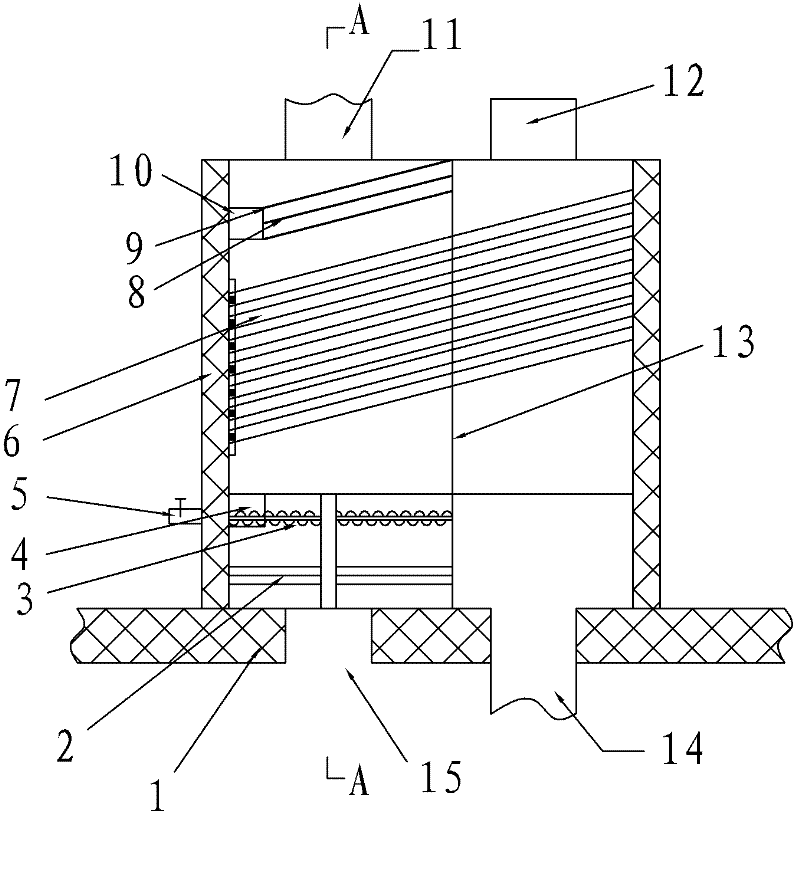
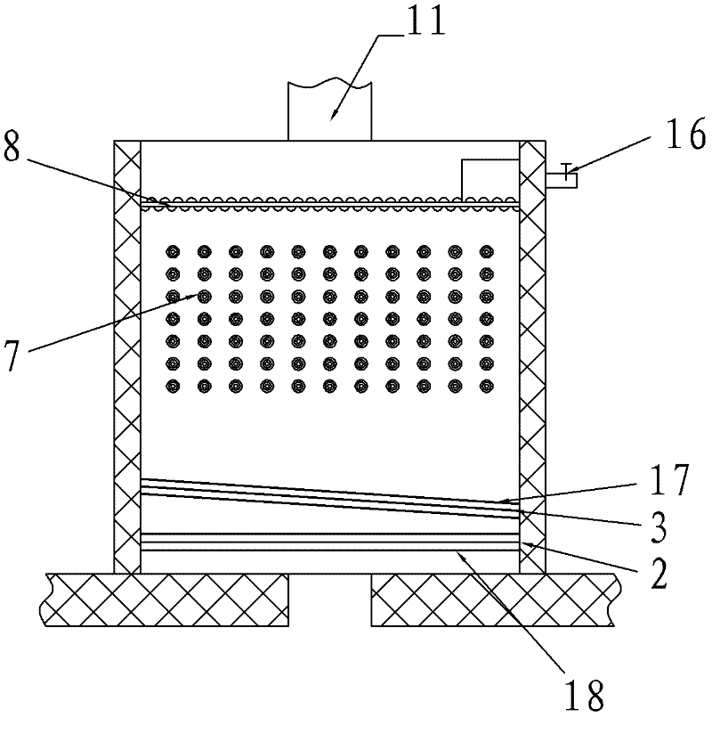
[0025] Such as figure 1 , figure 2 The shown oil-collecting and energy-saving device includes a box body 6, and the box body 6 is divided into two relatively independent spaces on the left and right by a sealing partition 13. The left part is an exhaust gas channel, and the right part is a fresh air channel; the box body 6 is in The bottom of the waste gas channel is provided with a waste gas inlet 15, and the top is provided with a waste gas discharge port 11. In the waste gas channel, a filter screen 2, a downward oil collecting device 3, a plurality of heat pipes 7 arranged in an array, and an upward collecting device are sequentially arranged in the waste gas channel. oil device 8, these heat pipes 7 enter the fresh air passage through the sealing partition 13; the box body 6 is provided with a fresh air inlet 12 above the fresh air passage, and a fresh air outlet 14 is provided below, and the above-mentioned multiple air outlets arranged in an array are arranged in the f...

Embodiment 2

[0029] A sizing machine, comprising the oil-removing and energy-saving device described in Embodiment 1, the waste gas inlet 15 of the oil-removing and energy-saving device communicates with the exhaust port of the sizing machine, and the fresh air outlet 14 of the oil-removing and energy-saving device is connected to the sizing machine The air inlet is connected.

Embodiment 3

[0031] A dryer, comprising the oil-removing and energy-saving device described in Embodiment 1, the exhaust gas inlet 15 of the oil-removing and energy-saving device communicates with the exhaust gas port of the dryer, and the fresh air outlet 14 of the oil-removing and energy-saving device is connected to the The air inlet of the dryer is connected.


PUM


Abstract

The invention discloses a dryer with an oil removing and collecting energy-saving device, which comprises the oil removing and collecting energy-saving device. The oil removing and collecting energy-saving device comprises a box body. The box body is divided into two left and right independent spaces through a sealing diaphragm; the left part of the box body is used as a waste gas passage; the right part of the box body is used as a fresh air passage; a waste gas inlet is arranged in the box body and below the waste gas passage; a waste gas discharge outlet is arranged in the box body and above the waste gas passage; a filter screen, a lower oil removing and collecting device, a heat pipe and an upper oil removing and collecting device are sequentially arranged in the waste gas passage from bottom to top; the heat pipe passes through the sealing diaphragm to enter the fresh air passage; a fresh air inlet is arranged in the box body and above the fresh air passage; a fresh air outlet is arranged in the box body and below the fresh air passage; the heat pipe is arranged in the fresh air passage; the waste gas inlet of the oil removing and collecting energy-saving device is communicated with a waste gas port of the dryer; and the fresh air outlet of the oil removing and collecting energy-saving device is communicated with an air inlet of the dryer. Due to the adoption of the technical scheme, the adverse impact of oil substances in waste gas on a heat exchange surface is solved.

Description

technical field [0001] The invention belongs to the technical field of energy saving and purification, and in particular relates to a dryer with an energy-saving and purification-integrated design of an oil-collecting and energy-saving device. Background technique [0002] At present, setting machines and dryers are the main energy-consuming equipment in the textile printing and dyeing industry. According to the difference in setting temperature and exhaust gas emission, each setting machine has about 300,000-500,000 kcal / hour of heat wasted due to exhaust emissions. Under the macro background of energy saving and emission reduction, it is of great practical significance to install energy-saving devices at the exhaust outlets of setting machines and dryers. [0003] Exhaust gas from sizing machines and dryers contains a lot of fumes and fibers. Most of the current energy-saving devices ignore the impact of oily substances in the exhaust gas on the heat exchange surface of he...

Claims


Application Information

Patent Timeline
Patent Type & Authority Applications(China)
IPC IPC(8): F26B25/00D06C7/02
CPCF28D15/0275
Inventor 唐国本金德高
Owner DEQING HENGXIN ENERGY SAVING TECH
Why Eureka
Try Eureka