Photoelectric oil smoke transducer

A fume sensor, photoelectric technology, applied in instruments, scientific instruments, material analysis through optical means, etc., can solve the problem of complicated preparation of clean air, and achieve the effect of reducing the possibility of head pollution

Active Publication Date: 2017-12-15
NINGBO FOTILE KITCHEN WARE CO LTD
View PDF15 Cites 0 Cited by
  • Summary
  • Abstract
  • Description
  • Claims
  • Application Information

AI Technical Summary

Problems solved by technology

The disadvantage of the above method is that an external clean air source is required, the preparation of clean air is very complicated, and an external power source is required to pass the clean air into the device

Method used


Image

  • Photoelectric oil smoke transducer
  • Photoelectric oil smoke transducer
  • Photoelectric oil smoke transducer

Examples


Embodiment 1

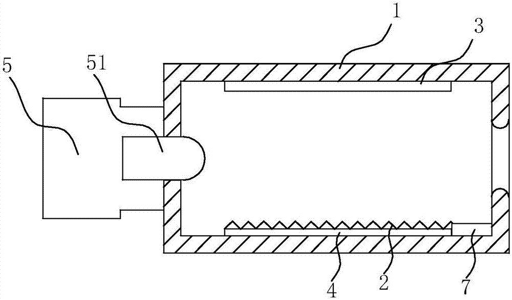
[0021] Such as figure 1 The photoelectric oil fume sensor shown includes a detection light emitting / receiving device 5, which has a head 51 capable of emitting or receiving detection light, the head is covered with a collimator tube 1 with a constant inner diameter, and the head 51 is sealed It is inserted into the opening at one end of the collimation tube 1 . The collimation tube 1 is provided with an electrostatic anti-oil pollution module, which includes a high-voltage pole 2 and a low-voltage pole 3, and the high-voltage pole 2 is attached to the insulating layer 4, and the insulating layer 4 is arranged on the lower part of the collimation tube 1; The low-voltage pole 3 is arranged on the upper part of the collimator tube 1 and placed opposite to the high-voltage pole 2; the high-voltage pole 2 is connected to the high-voltage generator 7, and the high-voltage generator 7 can be arranged inside the collimator tube or outside the collimator tube .

[0022] In this embod...

Embodiment 2

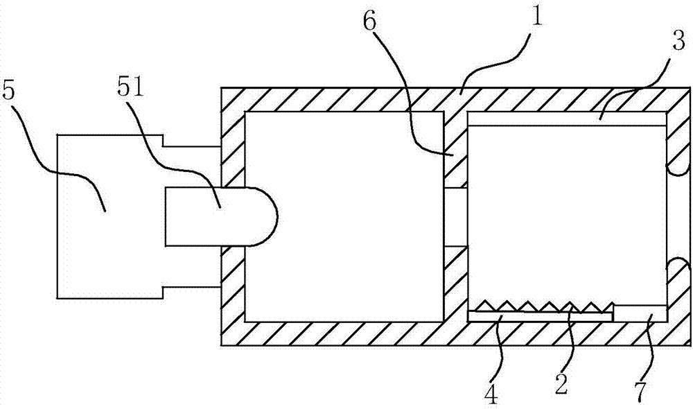
[0024] The difference from Embodiment 1 is that the inner diameter of the collimation tube is changed. In this embodiment, the change of the inner diameter is realized in the following way: a blocking plate 6 is provided in the middle of the collimating tube, and a hole is opened on the blocking plate. Through holes, the blocking plate 6 divides the interior of the collimation tube into two spaces. The electrostatic anti-oil pollution module can only be arranged in one of the spaces, and the electrostatic anti-oil pollution module can also be arranged in both spaces. In this embodiment, the electrostatic anti-oil pollution module is only arranged in a section of space away from the head 51. See figure 2 shown.

[0025] The above-mentioned collimation tube is designed with a deep cavity so that the head 51 of the detection light emitting / receiving device 5 will not be directly exposed to the oil fume flow, and the installation end of the head 51 is sealed so that the inside of...

Embodiment 3

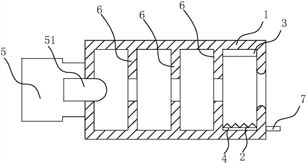
[0028] Different from Embodiment 2, there are multiple blocking plates 6 in the above-mentioned collimating tube, arranged at intervals, three in this embodiment, and the diameters of the through holes on two adjacent blocking plates 6 can be the same or not. Same, the diameters of the through holes are the same in this embodiment. Three blocking plates 6 arranged at intervals divide the interior of the collimation tube into four spaces, and the anti-static anti-oil module can be installed in only one or two or three spaces, or static electricity can be installed in all four spaces. Anti-oil pollution module, in this embodiment, the electrostatic anti-oil pollution module is only set in a section of space farthest from the head 51, see image 3 shown.

[0029] The design of this multiple variable-diameter labyrinth makes the inner diameter of the collimation tube expand and shrink multiple times. When expanding, the oil fume obtains a radial diffusion driving force, and most ...


PUM


Abstract

The invention relates to a photoelectric oil smoke transducer, which includes a detection light emitting / receiving apparatus. The apparatus has a head capable of emitting / receiving detection light. A collimator tube sleeves the head and is characterized being internally provided with a static oil-stain-resistant module. Compared with an oil smoke transducer, the oil smoke transducer is provided with the collimator tube, which is internally provided with a static oil-stain-resistant module. When the collimator tube reaches a collimated light path, oil smoke particles in the collimator tube can be effectively removed, so that the possibility that the head is polluted is greatly reduced. The smoke transducer has a good effect on prevention of dust and oil smoke pollution. Furthermore, the collimator tube makes an optical path channel coincide with an oil-stain-resistant channel, and the static oil-stain-resistant module doesn't affect the detection performance of the transducer. Static oil stain resistance requires low airflow speed of to-be-removed oil smoke and relatively low oil smoke concentration, and therefore, the required voltage is low. Thus, only a direct-current power supply which is low in cost is required.

Description

technical field [0001] The invention relates to a photoelectric oil fume sensor. Background technique [0002] A photoelectric sensor is a sensor that uses a photoelectric element as a detection element. It includes a detection light emitting device and a detection light receiving device. The detection light emitting device emits detection light, and the detection light receiving device receives the detection light. After the received detection light is refracted by the substance to be measured (such as oil smoke concentration), the light intensity Changes occur, and then the light intensity signal is further converted into an electrical signal by means of a photoelectric element. A photoelectric sensor is generally composed of three parts: a detection light emitting device, a detection light receiving device and a photoelectric element. The photoelectric detection method has the advantages of high precision, fast response, non-contact, etc., and has many measurable parame...

Claims


Application Information

Patent Timeline
Patent Type & Authority Applications(China)
IPC IPC(8): G01N21/53
CPCG01N21/534G01N2201/0642
Inventor 徐钦龙戴九松茅忠群诸永定刘戈
Owner NINGBO FOTILE KITCHEN WARE CO LTD
Why Eureka
Try Eureka