Cyclonic separation device with acceleration ramp

a technology of cyclonic separation and acceleration ramp, which is applied in the direction of auxillary pretreatment, cleaning filter means, separation processes, etc., can solve the problems of affecting performance, affecting power, and unsatisfactory and costly maintenance tasks for users, and achieve the effect of streamlining manufacturing and assembly costs

Inactive Publication Date: 2014-08-19
SEB SA
View PDF19 Cites 13 Cited by
  • Summary
  • Abstract
  • Description
  • Claims
  • Application Information

AI Technical Summary

Benefits of technology

[0011]This type of acceleration ramp combined with the separation chamber makes it possible to avoid an excessively large chamber by disassociating the acceleration function from the chamber itself. In other words, for a chamber of a predetermined size, this ramp increases the effectiveness of dust and debris separation by increasing their speed. This aspect is even more significant when the device is used in vacuum cleaners with small motors that generate relatively low airflow speeds, such as upright vacuum cleaners, some of which operate on batteries.
[0015]Advantageously, the tube segment used to direct the airflow toward the air intake of the cyclonic chamber is linked to a vertical tube segment that decreases in size in the direction of air circulation. This vertical tube also assists in the acceleration of the airflow and allows this acceleration to continue over a significant distance, with the resulting gradual airflow acceleration limiting turbulence and thus also the accompanying noise.

Problems solved by technology

The problem with this solution is the fact that the paper filter bag eventually fills and must be replaced, which is an unpleasant and costly maintenance task for the user.
In addition, the filling of the bag negatively affects the performance of the vacuum cleaner since it results in a decrease in its power.

Method used


Image

  • Cyclonic separation device with acceleration ramp
  • Cyclonic separation device with acceleration ramp
  • Cyclonic separation device with acceleration ramp

Examples


Embodiment Construction

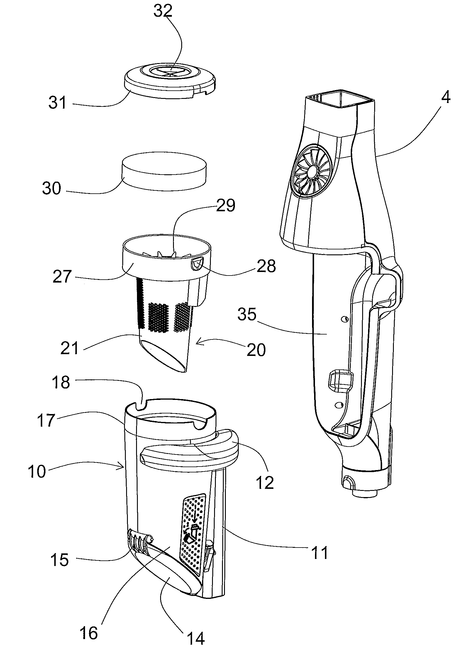
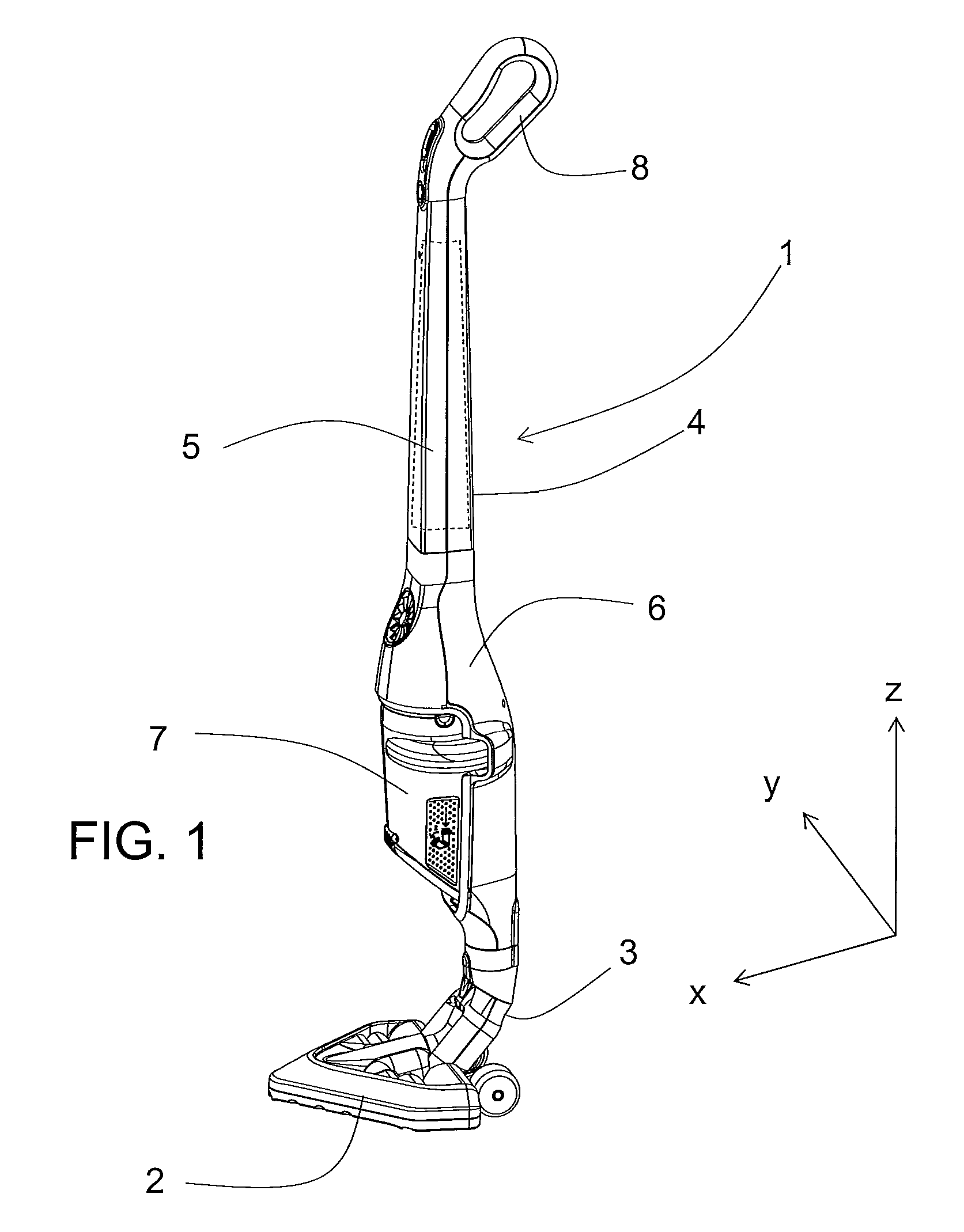
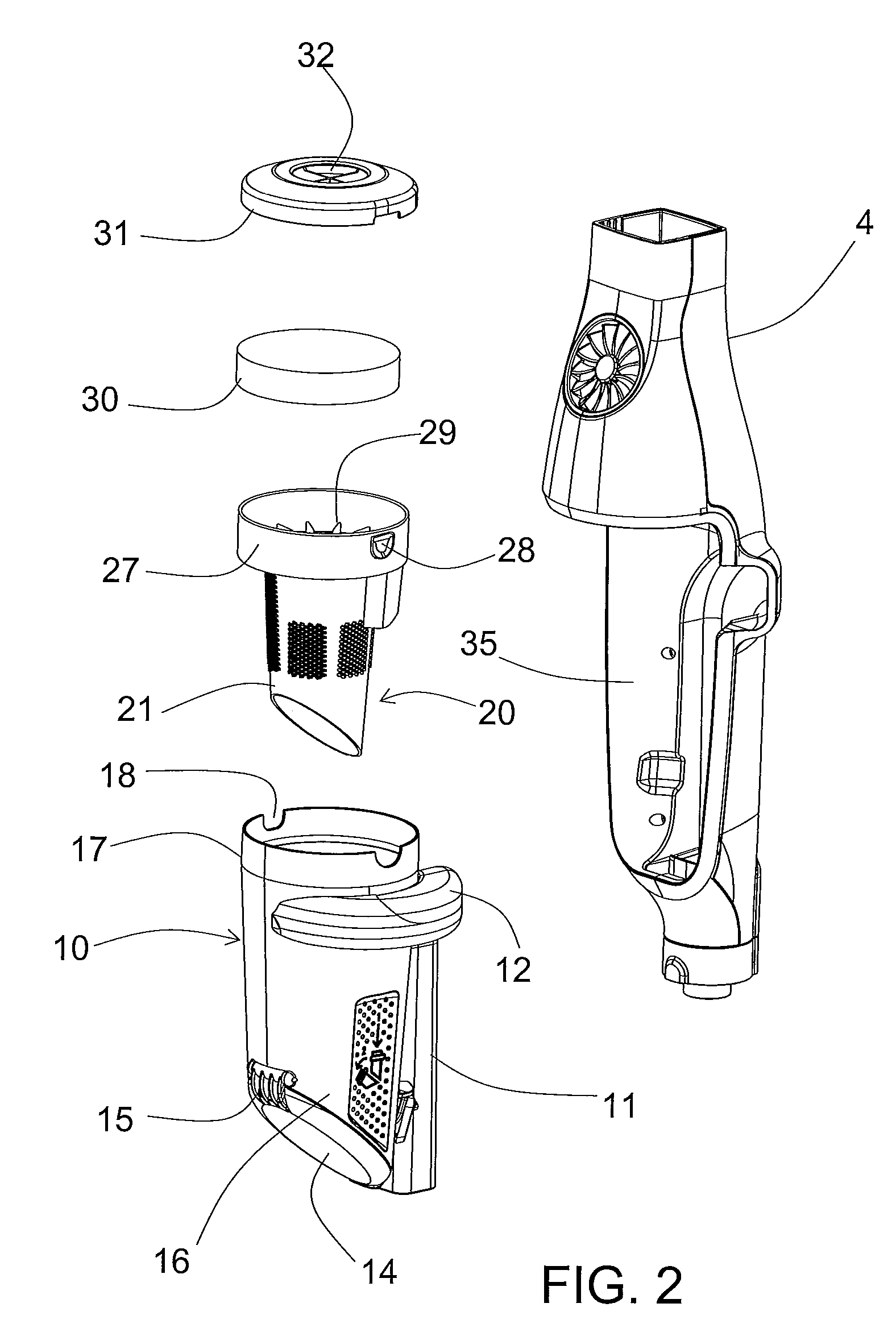
[0033]FIG. 1 depicts an upright vacuum cleaner (1), comprising a triangular suction device (2) connected to a handle (4) by an intermediate connective section (3). The term handle in this context refers not only to the longitudinal part of the device ending in a handle (8) at its upper end, but also to the various elements connected to the longitudinal part that form the frame, including a battery (5), a motor (6) and a cyclonic debris separation and storage device (7).

[0034]For the following description we will define axis “z” as the axis of the vacuum cleaner handle (4), corresponding to a roughly vertical axis in the vacuum cleaner's resting position depicted in FIG. 1, longitudinal axis “x” as the axis perpendicular to axis z bisecting the handle (4) from back to front along its plane of symmetry, and axis “y” as the transversal axis perpendicular to axes “x” and “z”. In the vacuum cleaner's resting position, axes “x” and “y” thus fall within a roughly horizontal plane. This pla...


PUM

PropertyMeasurementUnit
angleaaaaaaaaaa
angleaaaaaaaaaa
sizeaaaaaaaaaa

Abstract

A cyclonic separation device for dust and debris in vacuum cleaners, comprising a roughly cylindrical interior cyclonic chamber connected to an air intake, as well as a separator filter located in the central part of the interior chamber, comprising a tube segment to direct airflow to the air intake with this tube segment located around the roughly cylindrical interior cyclonic chamber, from a starting point to an end point near the air intake, with the cross-section of this tube segment near the end point being smaller than that near the starting point in order to form an acceleration ramp for the airflow between these two points.

Description

BACKGROUND OF THE INVENTION[0001]1. Field of the Invention[0002]The invention pertains to a structure defining a cyclonic chamber, which we will simply call the “bowl,” of a device for separation by inertia or cyclonic motion of dust and debris present in an airflow. It is particularly suited for use in a vacuum cleaner. It also pertains to a cyclonic separation device and a vacuum cleaner insofar as they comprise such a bowl.[0003]2. Description of the Prior Art[0004]In prior art, one type of dust and debris collection device for vacuum cleaners consists of a filter in the form of a paper bag, located between an intake tube for an airflow, containing dust and debris sucked from a surface to be cleaned and a suction fan unit. The problem with this solution is the fact that the paper filter bag eventually fills and must be replaced, which is an unpleasant and costly maintenance task for the user. In addition, the filling of the bag negatively affects the performance of the vacuum cle...

Claims


Application Information

Patent Timeline
Patent Type & Authority Patents(United States)
IPC IPC(8): A47L9/10A47L9/16A47L9/20B01D45/12B01D45/16
CPCA47L9/165B01D45/16A47L9/1666A47L9/1683A47L9/1691Y10S55/03A47L9/00A47L9/10A47L9/16
Inventor SOEN, ALAINREYNARD, SYLVAIN
Owner SEB SA
Why Eureka
Try Eureka