Mechanical seal device

A mechanical seal device and mounting piece technology, applied in the direction of engine seals, mechanical equipment, engine components, etc., can solve the problems of low pumping ring slinging efficiency, slow cooling liquid circulation, etc., to reduce the working temperature, accelerate the circulation, Increases the effect of the water throwing effect

Active Publication Date: 2012-01-25
江苏华青流体科技有限公司
View PDF6 Cites 9 Cited by
  • Summary
  • Abstract
  • Description
  • Claims
  • Application Information

AI Technical Summary

Problems solved by technology

The efficiency of the pumping ring with this structure is low, and the circulation of the coolant is slow

Method used


Image

  • Mechanical seal device
  • Mechanical seal device
  • Mechanical seal device

Examples


Embodiment Construction

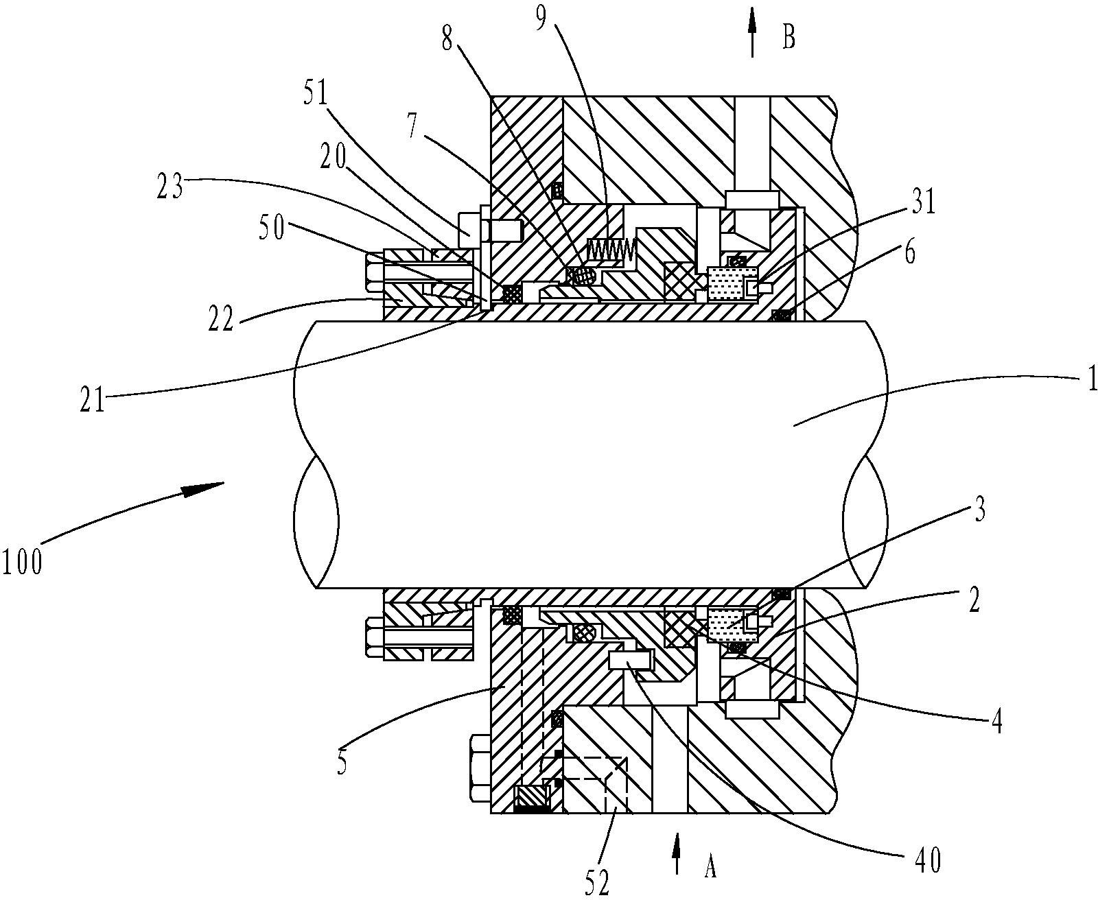
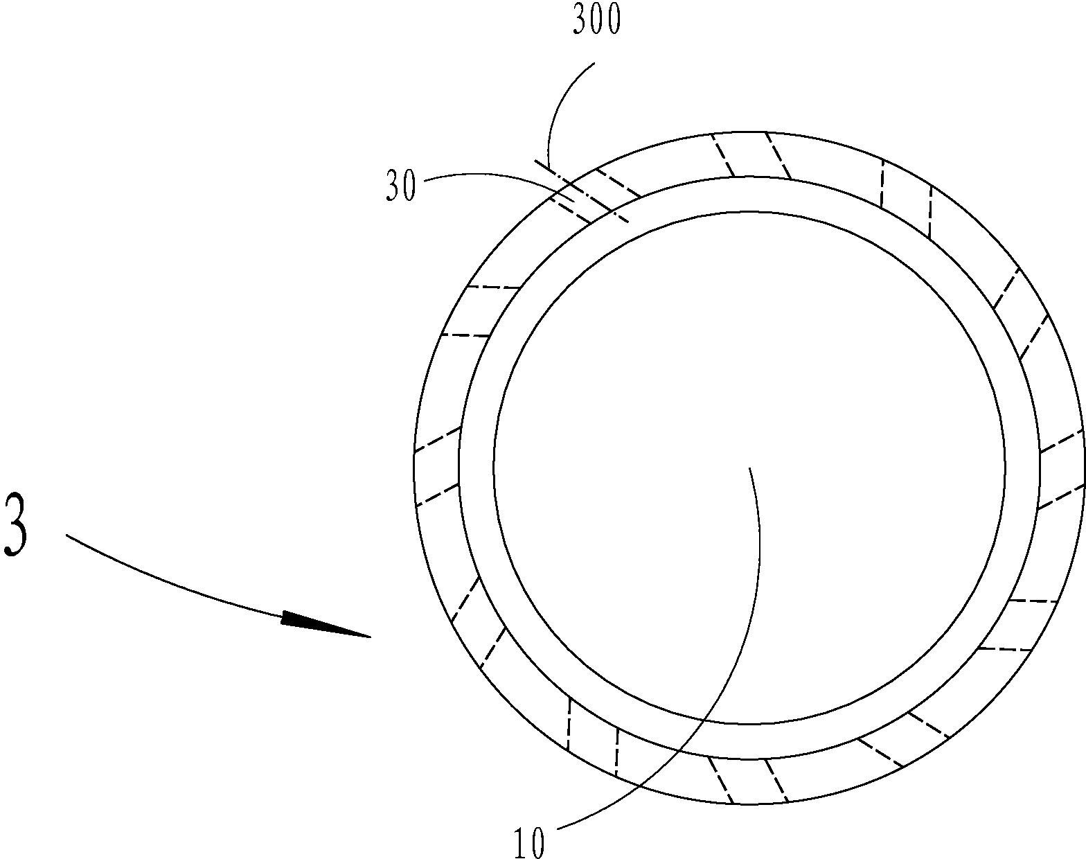
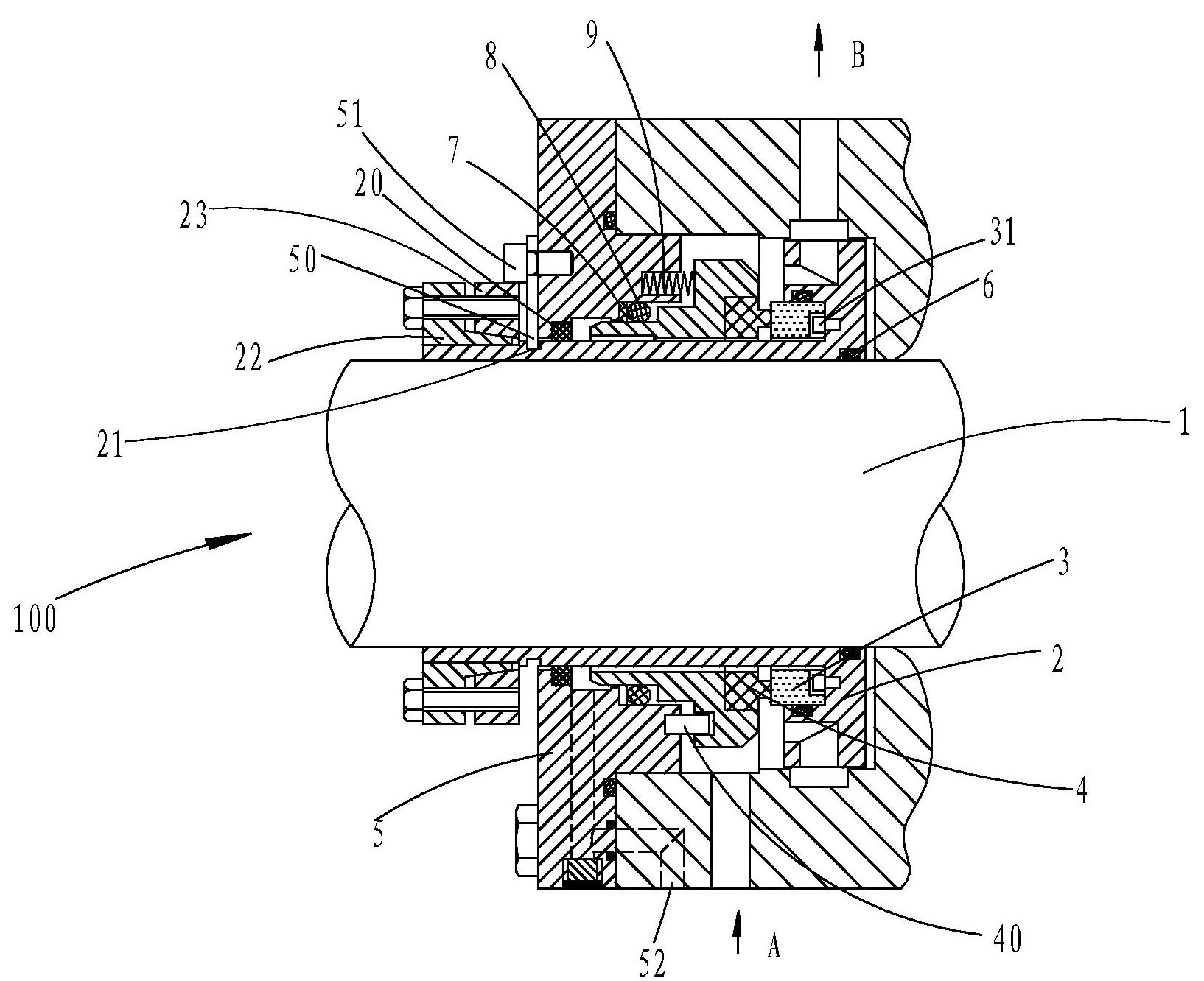
[0010] see figure 1 and figure 2 , a mechanical seal device 100, which includes: a rotating shaft 1, a shaft sleeve 2 installed on the rotating shaft 1, a pumping ring 3 integrally formed with the shaft sleeve, a static ring 4 frictionally fitted with the pumping ring 3, and a static ring mounted on the static ring The gland 5 on 4, the sleeve O-ring 6 is arranged between the shaft sleeve 2 and the rotating shaft 1, the gasket 7 and the static ring O-ring 8 are arranged between the gland 5 and the static ring 4, so A spring 9 is provided between the gland 5 and the static ring 4, and an anti-rotation pin 40 is provided between the gland 5 and the static ring 4, thereby preventing the gland 5 from rotating relative to the static ring 4. The gland 5 A cut-off ring 20 is provided between the shaft sleeve 2, and a mounting piece 50 is provided on one side of the gland 5, and the mounting piece 50 is fixed to the gland 5 by a hexagon socket head set screw 51, and the shaft The s...


PUM


Abstract

The invention discloses a mechanical seal device. The mechanical seal device provided by the invention comprises a rotating shaft, a shaft sleeve, a pimping ring, a stationary seal ring and a gland, wherein a shaft sleeve O-shaped circle is arranged between the shaft sleeve and the rotating shaft, a gasket and a stationary seal ring O-shaped circle are arranged between the gland and the stationary seal ring; a spring is arranged between the gland and the stationary seal ring, a stop pin is arranged between the gland and the stationary seal ring, a cut-off ring is arranged between the gland and the shaft sleeve, and one side of the gland is provided with a mounting piece; the shaft sleeve is provided with a clamping groove used for clamping the mounting piece, an upper expanding ring and a lower expand ring are arranged one side of the shaft sleeve, on which the mounting piece is arranged, and the pumping ring is provided with multiple radial liquid outlets; the radial liquid outlets are arranged into an array in a circumferential direction of the pumping ring, and the centre line of the radial liquid outlets does not pass through the centre of the rotating shaft; the centre line of the radial liquid outlets and the diameter of the rotating shaft form an angle of 20 degrees-30 degrees, and the gland is also provided with a leakage port. The mechanical seal device provided by the invention has the advantages of accelerating the circulation of cooling liquid, and effectively reducing the sealing work temperature.

Description

technical field [0001] The invention relates to a mechanical sealing device. Background technique [0002] In industries such as petroleum refining and chemical industry, more than 80% of the rotating equipment for transporting liquid media adopt mechanical seals. The zero escape, high reliability, long life and low wear of mechanical seals are the research and development directions in the field of mechanical seals. In general mechanical seal devices, it is required that the seal coolant or isolation buffer can circulate to take away the heat generated by the seal end face and reduce the seal working temperature. There are generally three ways to promote the circulation of the sealing liquid: (1) Add a small pipeline circulation pump to the system pipeline to complete the circulation; (2) Use the thermosiphon effect to form a natural flow cycle; (3) Add a pumping pump to the seal. The rotating part of the effect - the pumping ring, to complete the sealing fluid circulation...

Claims


Application Information

Patent Timeline
Patent Type & Authority Applications(China)
IPC IPC(8): F16J15/16F16J15/34
Inventor 王伟
Owner 江苏华青流体科技有限公司
Why Eureka
Try Eureka