Energy-saving umbrella water throwing device

An energy-saving, umbrella technology, applied in the direction of furnace type, drying gas arrangement, dry product type, etc., can solve the problems of unable to dry umbrella cloth, unfavorable people's travel, waste, etc., achieve high water removal efficiency, increase water rejection effect, better effect

Pending Publication Date: 2021-02-09
徐守珍
View PDF10 Cites 2 Cited by
  • Summary
  • Abstract
  • Description
  • Claims
  • Application Information

AI Technical Summary

Problems solved by technology

[0002] In daily life, people will use umbrellas on rainy days, which provide great convenience for us to appear, and when people need to go to some shopping malls or company office buildings, etc., because the ground in these places is very smooth, umbrellas When the water on the ground falls on the ground, the ground will become more slippery, and people are prone to slipping when walking, which is not conducive to people's travel.
[0003] In this regard, special staff will distribute some plastic bags before people enter these places, and umbrellas will be covered with plastic bags. Although this method can prevent the water on the umbrellas from falling on the ground, it will consume a lot of plastic bags. , and people generally throw away these plastic bags after they are used up, which causes great waste and pollutes the environment. There are also some umbrella drying equipment on the market now, but when these devices are in use, they only dry the umbrellas through the dryer. drying, and cannot focus on drying the umbrella cloth with rainwater attached, the drying efficiency is low, how to solve these problems is what we need to consider

Method used


Image

  • Energy-saving umbrella water throwing device
  • Energy-saving umbrella water throwing device
  • Energy-saving umbrella water throwing device

Examples


Embodiment 1

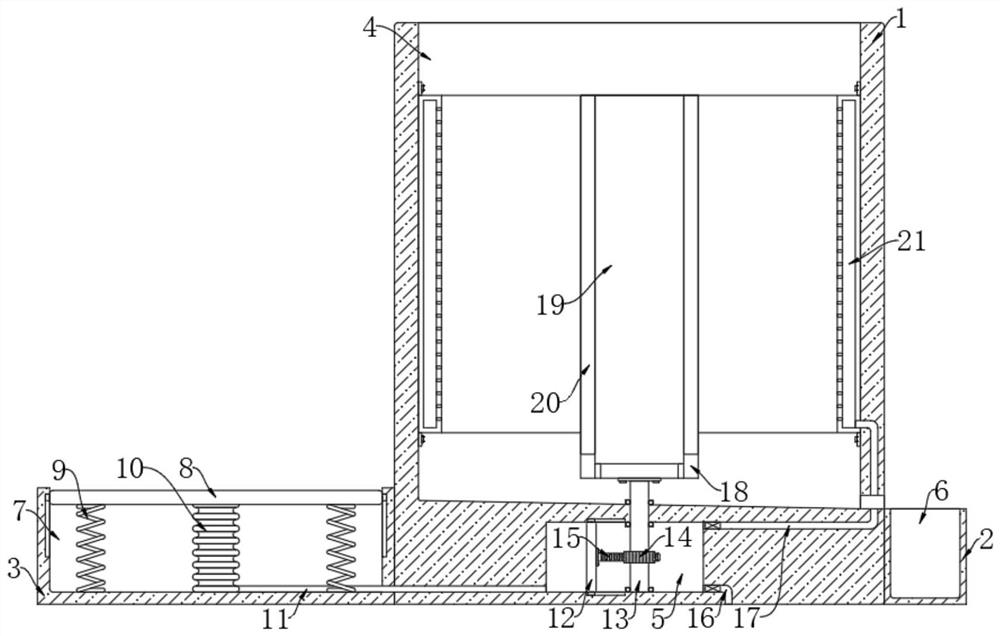
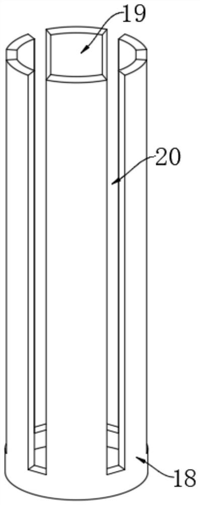
[0022] refer to Figure 1-2 , an energy-saving umbrella water throwing device, comprising a housing 1, the upper end of the housing 1 is provided with a rotating groove 4, the housing 1 is provided with a moving chamber 5, the moving chamber 5 is located below the rotating groove 4, the housing 1 The right side wall is fixedly connected with a connecting block 2, the upper end of the connecting block 2 is provided with a collection tank 6, the left side wall of the housing 1 is fixedly connected with a fixed block 3, and the upper end of the fixed block 3 is provided with a compression groove 7, and the upper end of the rotating groove 4 There is a water outlet connected to the outside world on the inner wall on the right side;

[0023] The trigger mechanism, the trigger mechanism includes a pressing plate 8 horizontally arranged in the compression groove 7, the pressing plate 8 is slidingly connected with the inner wall of the compression groove 7, and the lower end of the pr...

Embodiment 2

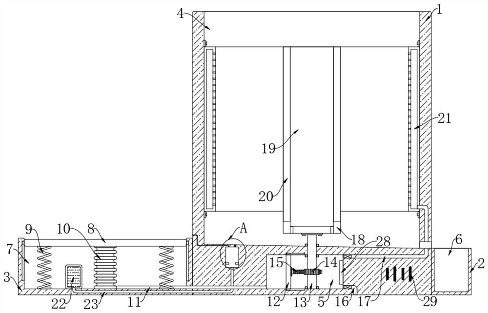
[0030] refer to Figure 3-4 The difference between this embodiment and Embodiment 1 is that the inner bottom of the compression groove 7 is fixedly connected with a liquid storage bag 22, and the liquid storage bag 22 is filled with mercury, and the housing 1 is provided with a conductive cavity 24, and the conductive cavity 24 Conductive blocks 25 are installed on both sides of the inner wall, the conductive cavity 24 communicates with the liquid storage bag 22 through the liquid pipe 23, the conductive cavity 24 communicates with the rotating groove 4 through the air vent 27, and the conductive cavity 24 communicates with the rotating groove 4 through the air outlet 26 Connected, the air outlet 26 is provided with a one-way valve, and the one-way valve can ensure that the air outlet 26 is only air-out and not inhaled. A heating plate 28 is installed on the right side inner wall of the moving chamber 5, and a power supply 29 is provided in the housing 1. The conductive block ...


PUM


Abstract

The invention discloses an energy-saving umbrella water throwing device. The device comprises a shell, a rotating groove is formed in the upper end of the shell, a moving cavity is formed in the shell, the moving cavity is located below the rotating groove, a connecting block is fixedly connected to the right side wall of the shell, a collecting groove is formed in the upper end of the connectingblock, a fixing block is fixedly connected to the left side wall of the shell, a compression groove is formed in the upper end of the fixing block, and a water outlet communicating with the outside isformed in the inner wall of the right side of the rotating groove. The device throws an umbrella to throw away rainwater attached to the umbrella, multiple layers of umbrella cloth are separated through multiple openings, water throwing is conducted on each layer of umbrella cloth, airflow can be sprayed to the umbrella cloth to spray rainwater on the umbrella cloth, a heating plate is arranged in the moving cavity, the sprayed airflow becomes hot air, the rainwater on the umbrella cloth is dried, and the rainwater removing efficiency is improved.

Description

technical field [0001] The invention relates to the field of umbrella water removal devices, in particular to an energy-saving umbrella water removal device. Background technique [0002] In daily life, people will use umbrellas on rainy days, which provide great convenience for us to appear, and when people need to go to some shopping malls or company office buildings, etc., because the ground in these places is very smooth, umbrellas When the water on the ground falls on the ground, the ground will become more slippery, and people are prone to slipping when walking, which is not conducive to people's travel. [0003] In this regard, special staff will distribute some plastic bags before people enter these places, and umbrellas will be covered with plastic bags. Although this method can prevent the water on the umbrellas from falling on the ground, it will consume a lot of plastic bags. , and people generally throw away these plastic bags after they are used up, which caus...

Claims


Application Information

Patent Timeline
Patent Type & Authority Applications(China)
IPC IPC(8): F26B11/08F26B5/08F26B3/02F26B21/00F26B25/00F26B25/16
CPCF26B3/02F26B5/08F26B11/08F26B21/001F26B21/004F26B25/00F26B25/16F26B2210/10
Inventor 徐守珍
Owner 徐守珍
Why Eureka
Try Eureka