

Field hydrostatic test method for water-proof system of building deformation joint
A technology of hydraulic test and deformation joint, which is applied in the direction of using liquid/vacuum for liquid tightness measurement, etc., can solve the problems of high operation difficulty, complicated device, high cost, etc., and achieves improved reliability, simple structure and low cost. Effect
Inactive Publication Date: 2012-01-25
吴兆圣
View PDF5 Cites 21 Cited by
- Summary
- Abstract
- Description
- Claims
- Application Information
AI Technical Summary
Problems solved by technology
The on-site hydrostatic test device for deformation joints is complex, expensive, and difficult to operate. Therefore, the
Method used
View moreImage
Smart ImageViewing Examples

Examples
 PUM
 Abstract
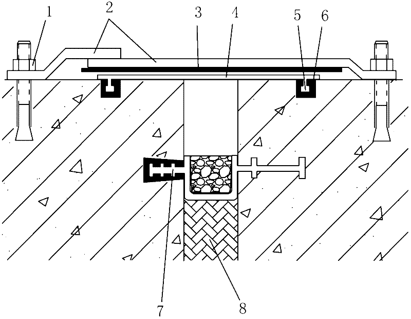
The invention discloses a field hydrostatic test method for a water-proof system of a building deformation joint. The method comprises the following steps of: cutting an anchor type externally attached water stop tie according to length of the deformation joint; when adhering the anchor type externally attached water stop tie, pre-forming a groove on the two sides of the deformation joint respectively, injecting an adhesive into the groove, and arranging anchor parts at the two wings of the anchor type externally attached water stop tie in the grooves; laying a polyethylene-polypropylene coiled material isolating layer on the anchor type externally attached water stop tie; then mounting a steel plate protection layer on concrete on the two sides of the deformation joint, wherein the steelplate protection layer is pressed on the polyethylene-polypropylene coiled material isolating layer to protect the anchor type externally attached water stop tie; opening two pipe joints which lead into the cavity of the deformation joint respectively; injecting water into the deformation joint through one pipe joint and discharging gas through the other pipe joint; and after the water is injected, sealing the pipe joint for discharging gas and performing hydrostatic test on the water-proof system of the deformation joint. In the method, the field hydrostatic test can be performed on the water-proof system of the deformation, so that the water-proof reliability is improved; and a simple structure and low cost are guaranteed.
Description
[technical field] [0001] The invention relates to the field of building waterproofing, in particular to an on-site hydraulic test method for the waterproofing system of building deformation joints. [Background technique] [0002] With the rapid development of underground engineering (underground engineering includes underground buildings, underground structures and subway engineering), especially large-scale underground engineering, the degree of electrification and automation in underground engineering continues to increase, and the requirements for waterproofing are becoming more and more important. If the underground project leaks, it will cause damage to the interior decoration, corrosion of equipment, frequent electrical accidents, damp and moldy materials, and damage to the health of personnel. The leakage of underground works has a serious impact on the safety of buildings. Long-term leakage causes damage to the alkaline environment inside the concrete, corrosion of s...
Claims
Login to View More Application Information
Patent Timeline
 IPC IPC(8): G01M3/02
Inventor吴兆圣
Owner吴兆圣