
High-pressure fuel injection tube having connection head and method for producing the same

A technology for high-pressure fuel and a manufacturing method, which is applied to fuel injection devices, fuel injection devices, special fuel injection devices, etc. with stress reduction measures, can solve problems such as tensile stress rise, circumferential cracks, cavitation, etc. The effect of eliminating the increase of the inner diameter and the elimination of valley cracks

Active Publication Date: 2012-01-25
USUI KOKUSAI SANGYO KAISHA LTD
View PDF4 Cites 2 Cited by
  • Summary
  • Abstract
  • Description
  • Claims
  • Application Information

AI Technical Summary

Problems solved by technology

Such a connection head 112 is formed by buckling by pressing a press member in the direction of the tube axis from the outside. The outer side expands, and on the inner peripheral surface of the head, due to the increase in the inner diameter and stress concentration, there is a recess (annular concave portion) 116 in which the tensile stress on the inner surface rises. When used in this state, however, there is a Cavitation caused by the high-pressure fluid during deployment and use will occur near the pocket, or cracks in the radial direction caused by fatigue damage will occur radially from the creases near the pocket on the head, Or the problem of cracks in the circumferential direction caused by fatigue damage around the cavity

Method used


Image

  • High-pressure fuel injection tube having connection head and method for producing the same
  • High-pressure fuel injection tube having connection head and method for producing the same
  • High-pressure fuel injection tube having connection head and method for producing the same

Examples


Embodiment 1

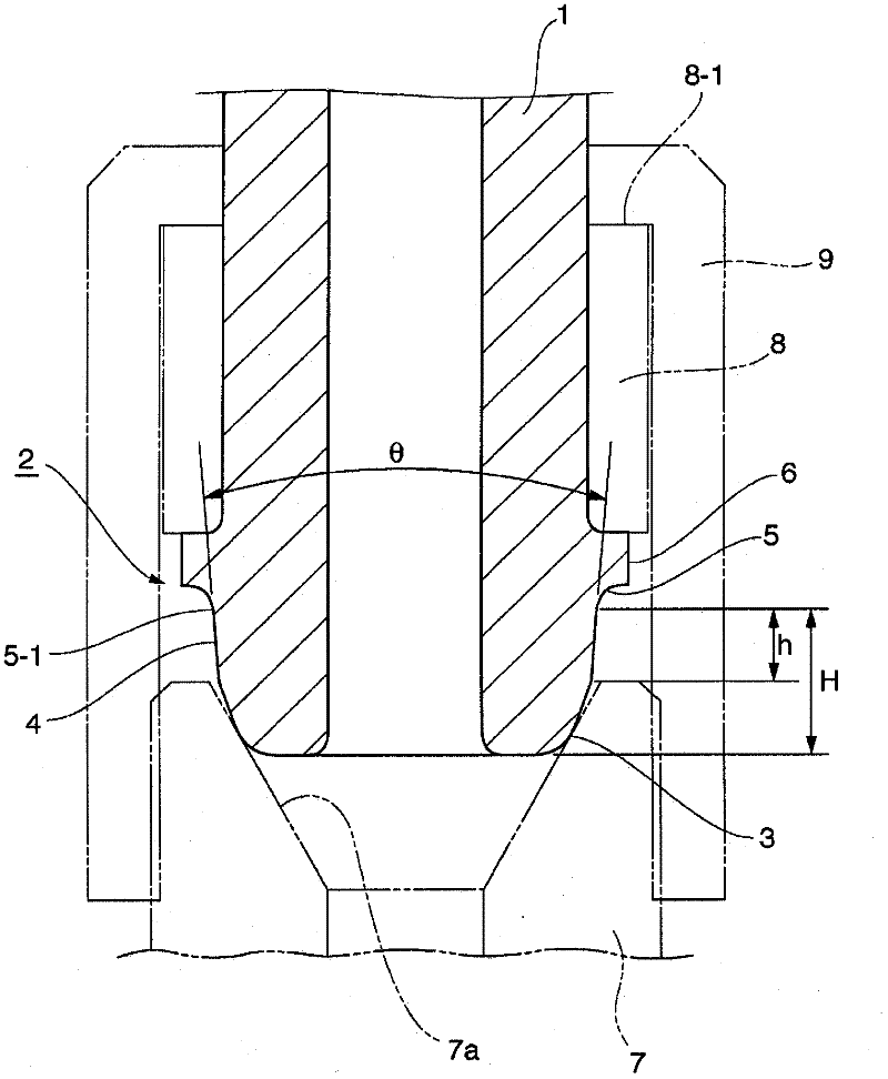
[0058] Using a thick-walled thin-diameter steel pipe (t / D=0.27) with a pipe diameter D of 9.0mm, an inner diameter Din of 4.0mm, and a wall thickness t of 2.5mm (material: equivalent to DIN ST52), the use is basically the same as Figure 7 The stamped components shown are the same stamped components, using and Figure 8 The same molding method as shown in the head molding method, manufacturing Figure 11 Shown is a high pressure fuel injection tube with a connecting head.

[0059] Regarding the pipe diameter D and wall thickness t of the thick-walled thin-diameter steel pipe in this example, the distance L in the axial direction from the end of the connection head obtained to the back of the annular flange part, the cylindrical shape The rear side opening angle θ of the face, the length h of the cylindrical face in the tube axis direction, the length H in the tube axis direction from the end of the connection head to the end of the rounded part on the side of the annular flan...

Embodiment 2

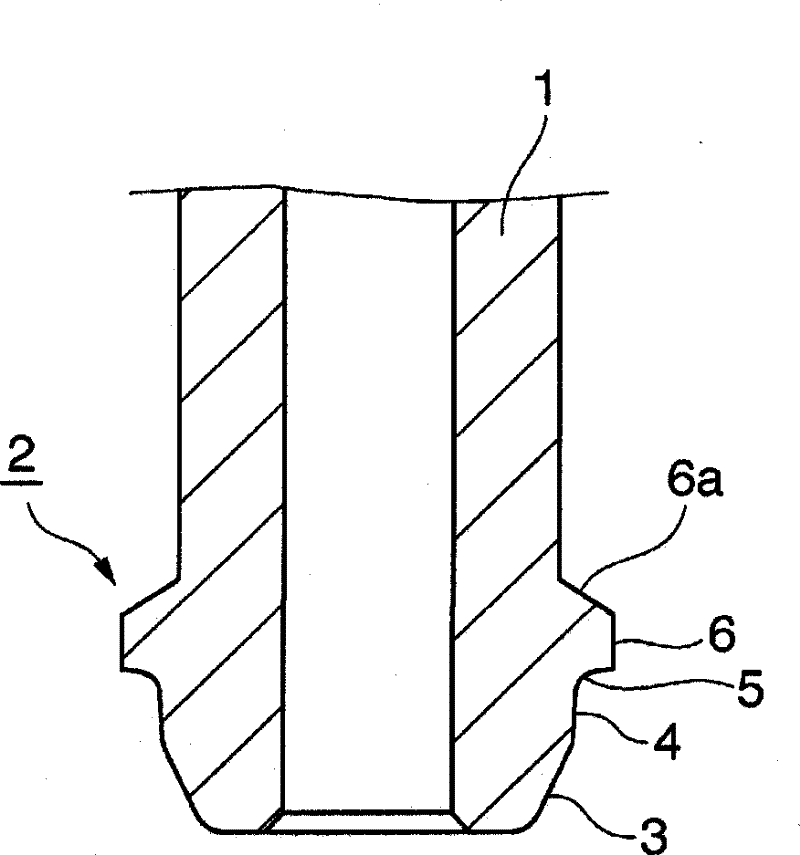
[0062] Using a thick-walled thin-diameter steel pipe (t / D=0.27) with a pipe diameter D of 9.0mm, an inner diameter Din of 4.0mm, and a wall thickness t of 2.5mm (material: equivalent to DIN ST52), the use is basically the same as Figure 7 The stamped components shown are the same stamped components, using and Figure 8 The same molding method as shown in the head molding method, manufacturing Figure 12 Shown is a high pressure fuel injection tube with a connecting head.

[0063] Regarding the pipe diameter D and wall thickness t of the thick-walled thin-diameter steel pipe in this example, the distance L in the axial direction from the end of the connection head obtained to the back of the annular flange part, the cylindrical shape The rear side opening angle θ of the face, the length h of the cylindrical face in the tube axis direction, the length H in the tube axis direction from the end of the connection head to the end of the rounded part on the side of the annular flan...

Embodiment 3

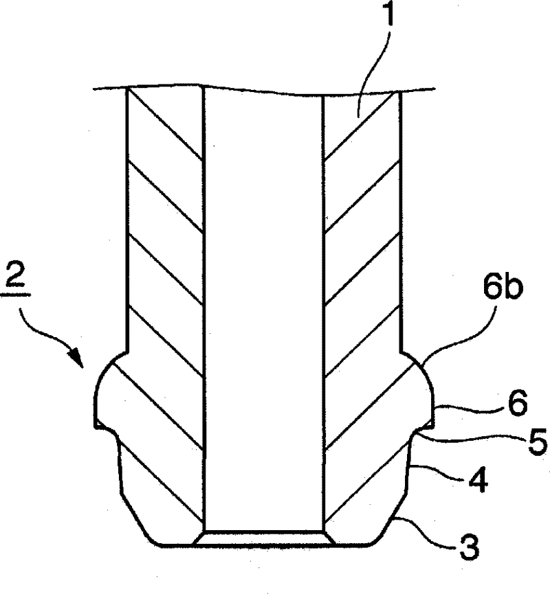
[0066] Using a thick-walled thin-diameter steel pipe (t / D=0.27) with a pipe diameter D of 9.0mm, an inner diameter Din of 4.0mm, and a wall thickness t of 2.5mm (material: equivalent to DIN ST52), the use is basically the same as Figure 7 The stamped components shown are the same stamped components, using and Figure 8 A high-pressure fuel injection pipe (omitted in the figure) having a connecting head is produced by the same forming method as the head forming method shown.

[0067] Regarding the pipe diameter D and wall thickness t of the thick-walled thin-diameter steel pipe in this example, the distance L in the axial direction from the end of the connection head obtained to the back of the annular flange part, the cylindrical shape The rear side opening angle θ of the face, the length h of the cylindrical face in the tube axis direction, the length H in the tube axis direction from the end of the connection head to the end of the rounded part on the side of the annular fl...


PUM

PropertyMeasurementUnit
angleaaaaaaaaaa
diameteraaaaaaaaaa
thicknessaaaaaaaaaa

Abstract

Provided is a high-pressure fuel injection tube which is resistant to fatigue breakdown, wherein a pocket portion is prevented from cracking when a head portion is molded; cracks occurring due to cavitation erosion are prevented; and tension stress which occurs in association with forming a pocket is prevented. The high-pressure fuel injection tube wherein the connection end of a thick-walled and small-diameter steel tube has a connection head composed of a seat surface, an annular flange portion, and a cylindrical surface which continues into the seat surface, is characterized by having a connection head wherein when viewed in cross section along the axial direction of the tube, the contours of the head from the end of the fillet portion of the annular flange to the seat surface form a cylindrical surface having a rear-side open angle (?) of 0 DEG < ? = 20 DEG with respect to the axis of the tube, and the ratio of the length (h) of the cylindrical surface in the axial direction of the tube to the length (H) from the end of the connection head to the end of the fillet part on the annular flange-side of the cylindrical surface is 0.33 = h / H = 0.85.

Description

technical field [0001] The present invention relates to, for example, the fuel supply path of a diesel internal combustion engine that is often used, preferably, the common rail and fuel injector of a diesel engine equipped with an accumulator fuel injection system, which are relatively small in diameter. The connection head structure of the high-pressure fuel injection pipe made of thick-walled steel pipe. Background technique [0002] In the past, as such a high-pressure fuel injection pipe with a connecting head, such as Figure 19 As shown by way of example, there is known a product having a connection head 112 at the connection end of a thick-walled steel pipe 111 made of a relatively thin diameter. Annular flanges 115 provided at intervals in the pipe axial direction, and an arc surface 114 connected to the aforementioned support surface 113 and tapering toward the front end of the aforementioned annular flange portion 115 are formed (refer to Patent Document 1). Fig...

Claims


Application Information

Patent Timeline
Patent Type & Authority Applications(China)
IPC IPC(8): F02M55/02
CPCF02M55/005F16L19/0286F16L19/028F02M2200/03F02M2200/04F02M2200/8053Y10T29/49231F02M55/02F02M63/00
Inventor 渡边荣司
Owner USUI KOKUSAI SANGYO KAISHA LTD
Learn More