Head part mechanism of glue dispenser

A dispensing machine and head technology, applied in the field of dispensing machine head mechanism, can solve the problems of reducing the processing efficiency of dispensing machine, dispensing processing, glue dispensing, etc., to improve dispensing quality and processing efficiency , Improve the dispensing rate, the effect of strong practicability

Active Publication Date: 2013-12-11
DONGGUAN ANDA AUTOMATIC EQUIP
View PDF6 Cites 0 Cited by
  • Summary
  • Abstract
  • Description
  • Claims
  • Application Information

AI Technical Summary

Problems solved by technology

The dispensing needles of the existing conventional dispensing machines are all set vertically. During the actual dispensing process, only the positions with large space on the PCB circuit board can be dispensed. If the thickness or height of the electronic components is large , and the existing dispensing needles can only be vertically up and down, so it is difficult to dispense glue to the dead angle position where the bottom of the electronic component contacts the PCB circuit board, which seriously affects the dispensing quality of the dispenser
[0003] In order to dispense the glue to the dead angle where the bottom of the electronic component is in contact with the PCB circuit board, someone tilts the dispensing head of the dispenser, but the inclined dispensing head can only touch one side of the electronic component. Dispensing processing can be performed on the side of the electronic component, but not on other sides of the electronic components. Usually, the dispensing process of each side is realized by changing the clamping position of the PCB circuit board on the workbench, which greatly reduces the dispensing process. machine processing efficiency

Method used


Image

  • Head part mechanism of glue dispenser
  • Head part mechanism of glue dispenser
  • Head part mechanism of glue dispenser

Examples


Embodiment Construction

[0021] In order to facilitate the understanding of those skilled in the art, the present invention will be further described below in conjunction with the embodiments and accompanying drawings, and the contents mentioned in the embodiments are not intended to limit the present invention.

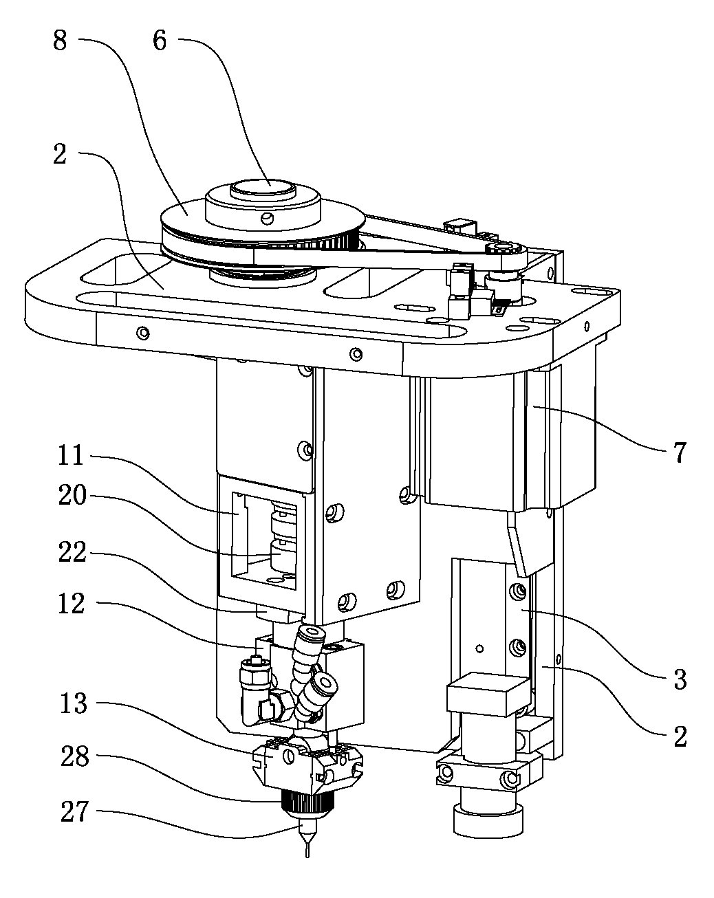
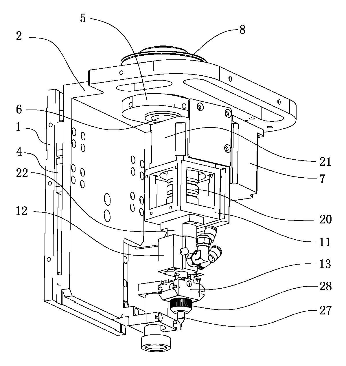
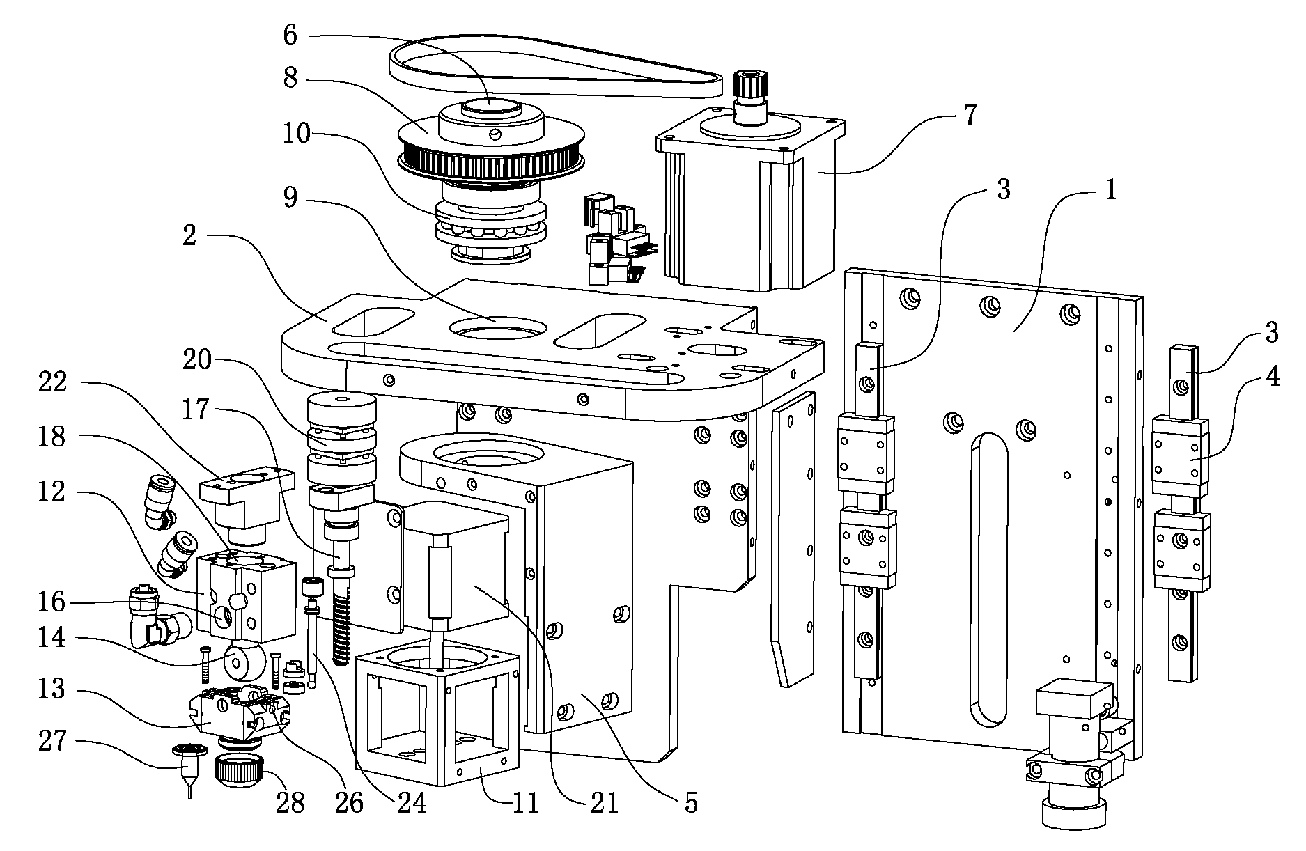
[0022] Such as Figure 1 to Figure 5 As shown, a head mechanism of a dispensing machine includes a head mounting base 1, a lifting base plate 2 and a corner dispensing device. The head mounting base 1 is equipped with a slide rail 3, and the slide rail 3 is movable. Block 4, the lifting base plate 2 is connected with the lifting slider 4, and also includes a rotating base 5, a main rotating shaft 6 and a rotating drive mechanism for driving the main rotating shaft 6 to rotate, the main rotating shaft 6 is rotatably mounted on the lifting base plate 2, and the rotating base 5 Connected with the lower part of the main rotating shaft 6 , the corner dispensing device is installed on the rotating...


PUM


Abstract

The invention relates to the technical field of glue dispensing processing of a PCB (Printed circuit board) circuit board, in particular to a head part mechanism of a glue dispenser. The head part mechanism of the glue dispenser comprises a head part installing seat, a lifting substrate and a corner glue dispensing device, wherein the head part installing seat is provided with a sliding rail which is movably provided with a lifting sliding block, and the lifting substrate is connected with the lifting sliding block. The head part mechanism of the glue dispenser also comprises a rotating base, a main rotating shaft and a rotating driving mechanism for driving the main rotating shaft to rotate, and the main rotating shaft can rotatablely arranged at the lifting substrate. The rotating base is connected with the lower part of the main rotating shaft, and the corner glue dispensing device is arranged at the rotating base. The head part mechanism of the glue dispenser not only can glue the blind angle position of a rectangular block-shaped electronic component but also can glue the blind angle position of a columnar electronic component, the clamping and putting position of a PCB (Printed circuit board) circuit board on a workbench does not need to be changed, the glue dispensing speed of glue dispensing processing is greatly increased, the glue dispensing quality and the processing efficiency of the glue dispenser are increased, and the practicality is strong.

Description

technical field [0001] The invention relates to the technical field of dispensing processing of PCB circuit boards, in particular to a head mechanism of a dispensing machine. Background technique [0002] Glue dispensing machine, also known as glue applicator, glue dropping machine, gluing machine, etc., is an automatic machine that controls fluid, drips and coats the fluid on the surface of the product or inside the product. The glue dispenser is mainly used for accurate pointing, injecting, coating, and dripping of glue, paint and other liquids in the product process to the precise position of each product, and can be used to achieve dots, lines, circles or arcs. The dispensing needles of the existing conventional dispensing machines are all set vertically. During the actual dispensing process, only the positions with a large space on the PCB circuit board can be dispensed. If the thickness or height of the electronic components is large , and the existing dispensing need...

Claims


Application Information

Patent Timeline
Patent Type & Authority Patents(China)
IPC IPC(8): B05C5/00
Inventor 刘飞张攀武
Owner DONGGUAN ANDA AUTOMATIC EQUIP
Why Eureka
Try Eureka