
Cutting unit for cutting sheet material

A technology for cutting units and thin slices, which is applied in metal processing and other directions, and can solve the problems of complex configuration and structure of disk blades

Active Publication Date: 2013-10-23
罗毅伯
View PDF9 Cites 0 Cited by
  • Summary
  • Abstract
  • Description
  • Claims
  • Application Information

AI Technical Summary

Problems solved by technology

[0007] The shortcoming of this kind of cutting unit is: the configuration structure of the blade support that comprises locking device and the disc blade supported on it is quite complicated

Method used


Image

  • Cutting unit for cutting sheet material
  • Cutting unit for cutting sheet material
  • Cutting unit for cutting sheet material

Examples


Embodiment Construction

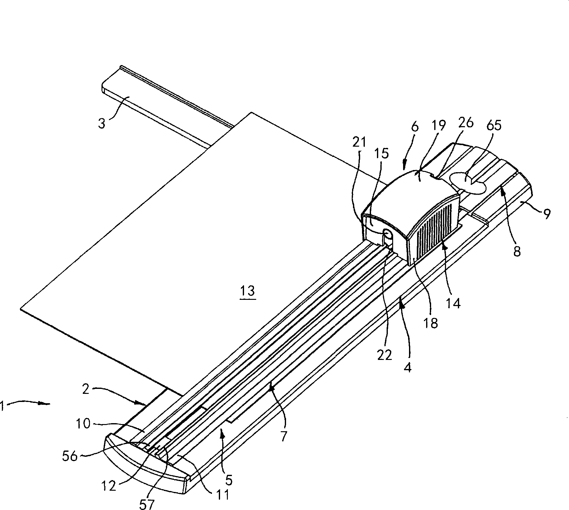
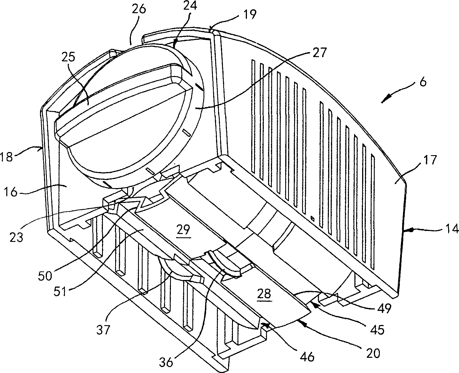
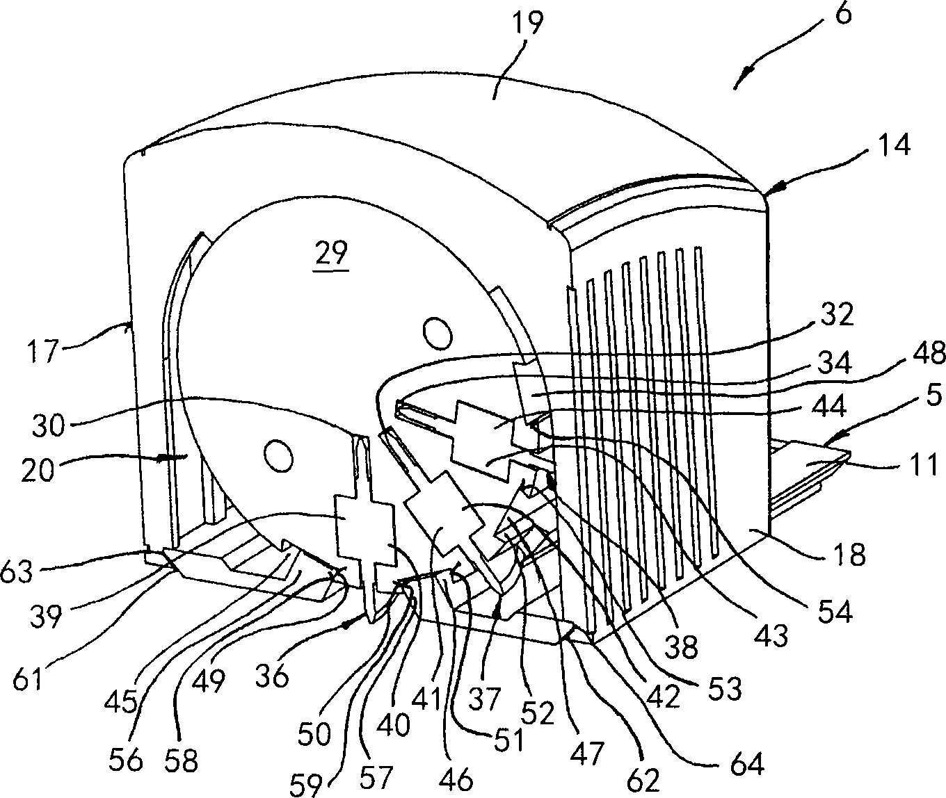
[0061] The cutting unit 1 shown in the drawing comprises a short beam-shaped foil support 2, wherein the contact rods 3 are folded out at right angles from the rear side of the foil support 2 facing away from the viewer. At a distance above the sheet support 2 there is a roll cutting device 4 which essentially comprises a support rail 5 and a cutting carrier 6 , which is movably supported on the support rail 5 . The support rail 5 is divided into a first rail assembly 7 and an adjacent second rail assembly, the first rail assembly 7 extends above the sheet support 2 with an offset (Offset), and the second rail assembly is formed into the sheet support. In the front end assembly 9 of the seat 2.

[0062] Both ends of the first rail assembly 7 are supported on the sheet support 2 by vertical coil springs (not shown), so that the first rail assembly 7 can be moved from the shown starting position (wherein the first rail assembly 7 There is an offset from the upper side of the sh...


PUM


Abstract

The invention discloses a cutting unit for cutting sheet material. The cutting unit comprises a sheet support and a roll cutting device combined with the sheet support. The roll cutting device comprises a support rail; a cutting carrier is movably supported on the support rail and comprises a blade support; the blade support is rotatably supported around a rotation shaft parallel to the support rail, and can be rotated manually; a disc blade on the blade support is freely rotatably supported around a blade shaft; the blade shaft extends and is vertical to the rotation shaft of the blade support; the disc blade is taken from an inactive position to a cutting position extending toward the sheet support; and a locking device supporting the blade support on the cutting position of the disc blade is provided, and configured to lock a clamp support element on the support rail and the blade support. When the disc blade is on the cutting position, the locking device supports the blade support on a rotation angle position for locking the rotation of the blade support; the support rail comprises a release part; and a support element locking the rotation of the blade support is not included.

Description

technical field [0001] The present invention relates to a cutting unit, in particular to a cutting unit for cutting sheet material. Background technique [0002] A manual cutting unit is being used to cut sheet material, such as paper and photo sheets for commercial and personal use, the unit generally comprising a sheet support configured as a base plate, the sheet support partially or completely containing the sheet material, and a cutting device , the cutting device is typically located on one side of the sheet support. As cutting devices, lever cutters and roll cutters are known. The latter has a straight support rail extending above and parallel to the foil support on which the blade carrier is movably supported. The disk blade is arranged in the blade carrier and thus is rotatably supported on a substantially horizontal axis, wherein the disk blade can be moved from a raised starting position to a lowered cutting position. After the disc blade is in the cutting posi...

Claims


Application Information

Patent Timeline
Patent Type & Authority Patents(China)
IPC IPC(8): B26D1/18B26D5/02
Inventor 罗毅伯
Owner 罗毅伯
Learn More