
Automatic gain control device, gain setting method of automatic gain control, wireless communication transceiver

A technology of automatic gain control and setting method, which is applied in gain control, amplification control, electrical components, etc., and can solve problems such as distortion, inability of demodulator to decode correctly, and saturated signal of analog-to-digital converter.

Active Publication Date: 2016-10-05
MICROCHIP TECH INC
View PDF4 Cites 0 Cited by
  • Summary
  • Abstract
  • Description
  • Claims
  • Application Information

AI Technical Summary

Problems solved by technology

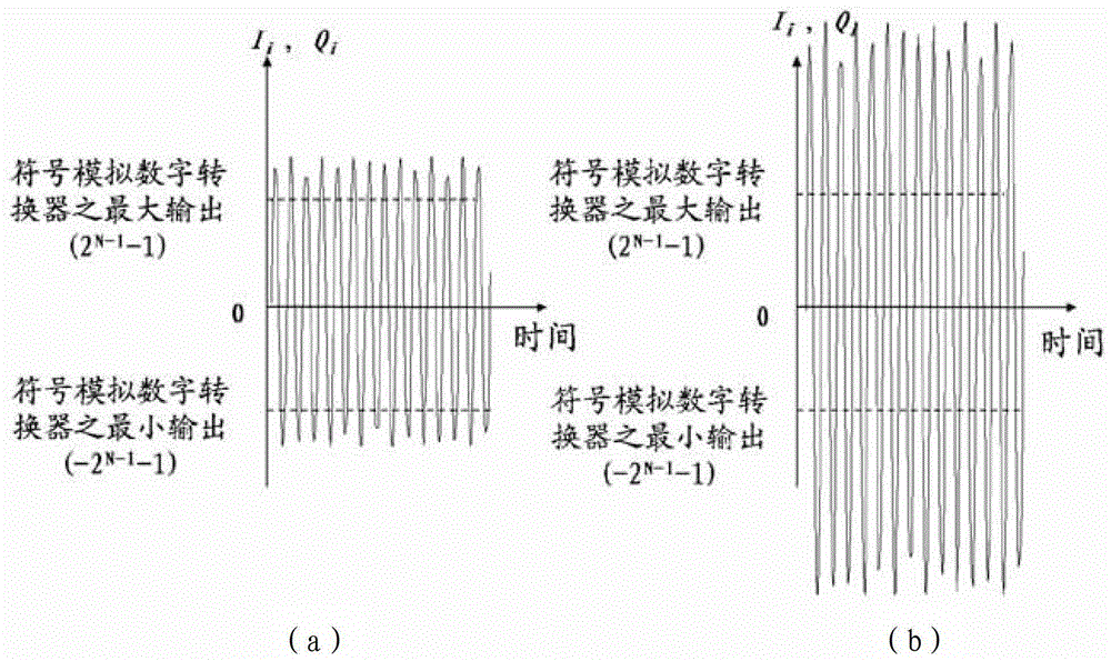
[0026] If the gain of the automatic gain control is too high, the output of the analog-to-digital converter will be saturated and cause signal distortion
If the AGC gain is too small, the ADC output is too small and the dynamic range of the ADC will be wasted, and the demodulator may not be able to decode correctly
The performance of the entire receiver system degrades in both cases

Method used


Image

  • Automatic gain control device, gain setting method of automatic gain control, wireless communication transceiver
  • Automatic gain control device, gain setting method of automatic gain control, wireless communication transceiver
  • Automatic gain control device, gain setting method of automatic gain control, wireless communication transceiver

Examples


Embodiment 1

[0093] now please refer to Image 6 , shown as a signed, 3-bit analog-to-digital converter via an unsigned-to-signed signal converter (i.e. -2 N / 2-1 Converter) output and power off a first embodiment. Briefly, for each first symbol signal (I i ) 2531 and the second symbol signal (Q i ) 2541, some power and amplitude indicators that are simply defined as "signal power too high" are defined as follows:

[0094] (a) Power index:

[0095] P msb _ k _ sat = True , if P i ≥ P msb _ k False ...

Embodiment 2

[0103] now please refer to Figure 7 , showing the utilization of 8 pairs of I provided by the present invention i with Q i The second embodiment of the automatic gain control method assisted by sample power statistics and amplitude statistics. For each of the 8 pairs of the first symbol signal (I i ) 2531 and the second symbol signal (Q i )2541, is to conduct statistics based on the above-mentioned simple indicators to confirm whether the setting of automatic gain control is extremely inappropriate. Figure 7 In the first column of , the six cases ((I)-(VI)) show cases where automatic gain control is extremely inappropriate. The corresponding "extra" gain adjustment signal value is expressed in dB in the second column. The third column includes the justification for "Using Additional Gain Adjustment". More specifically, the 8 pairs of first symbol signals (I i ) 2531 and the second symbol signal (Q i )2541 there are 6 pairs of saturation with the most significant bit....

Embodiment 3

[0106] now please refer to Figure 8 , showing that the use of the present invention provides the utilization of 16 pairs of I i with Q i The third embodiment of the automatic gain control method assisted by sample power statistics and amplitude statistics. For 16 pairs of I i with Q i Each pair of first symbol signals in (I i ) 2531 and the second symbol signal (Q i )2541, is to conduct statistics based on the above-mentioned simple amplitude statistical indicators to confirm whether the setting of automatic gain control is extremely inappropriate. This embodiment and Figure 7 Example 2 shown is slightly different. The main difference is that Figure 7 The power index P mentioned in msb_k_sat Not used in this example. exist Figure 8 In the first column of , the five cases ((I)-(V)) show cases where automatic gain control is extremely inappropriate. In the second column, the additional gain adjustment (Δ Aided ) signal value and provides some brief descriptions ...


PUM


Abstract

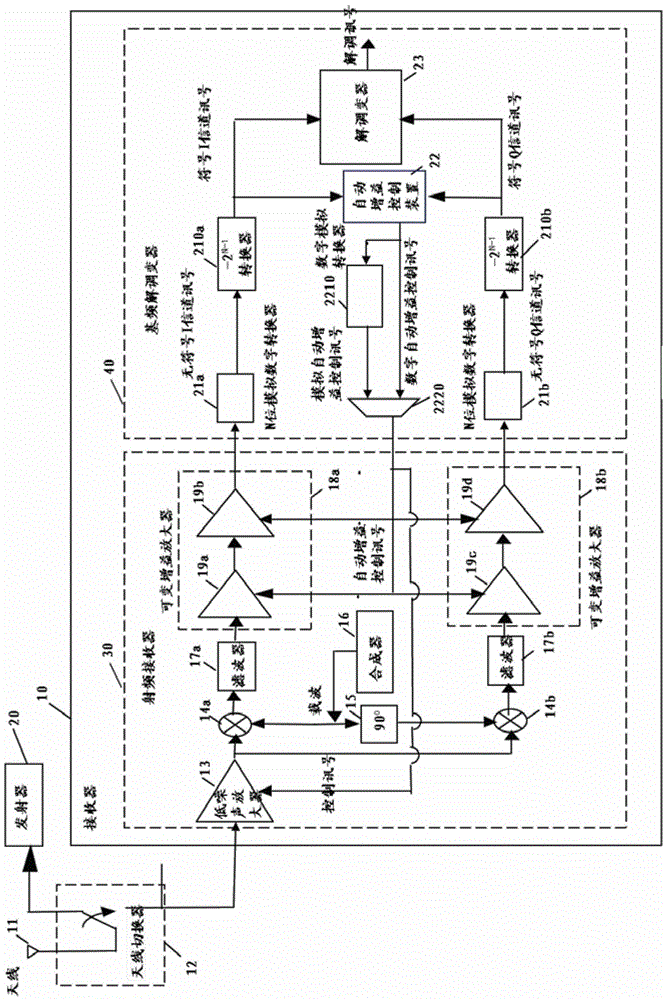
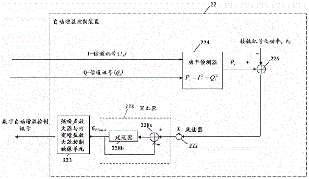
The invention discloses an automatic gain control device, an automatic gain control (AGC) gain setting method and a wireless communication receiver, which are applied to a wireless communication system. The fast and robust automatic gain control device of the invention includes: a first symbol signal (Ii), a second symbol signal (Qi), a power detector, an automatic gain control computing unit with auxiliary statistics, a subtractor, an averaging unit, an adder, a multiplier, an accumulator, And a low noise amplifier and a variable gain amplifier control imaging unit. The additional gain can be determined by the power statistics and amplitude statistics of the first symbol signal (Ii) and the second symbol signal (Qi) output by the paired N-bit analog-to-digital converter through the unsigned-to-sign signal converter The adjustment signal is used to control the state of the switch of the low noise amplifier and the gain of the variable gain amplifier, thereby providing an automatic gain control circuit.

Description

technical field [0001] The present invention relates to a fast and robust automatic gain control device and its operation method, not limited to the use of wireless local area networks (Wireless Local Area Networks, WLAN), in particular to an automatic gain control device that can perform automatic gain control when receiving signals device. Background technique [0002] The present invention relates to a wireless communication system, but is not limited to wireless local area networks (Wireless Local Area Networks, WLAN), especially 802.11a / b / g / n receiving baseband demodulators, which are various RF transceiver ICs ( Integrated Circuits) provides a fast and robust automatic gain control (AutoGain Control, AGC) function. In a typical WLAN environment, as the distance between the transmitter and receiver varies, the dynamic range of the received signal strength can be as high as 100dB. Automatic gain control circuits have been widely used in wireless local area network rece...

Claims


Application Information

Patent Timeline
Patent Type & Authority Patents(China)
IPC IPC(8): H03G3/30
CPCH03G3/3068H03G3/3078
Inventor 陈政宏杨惠民黄志清
Owner MICROCHIP TECH INC
Learn More