
Cable management system

A cable management and cable technology, which is applied in the field of computer systems, can solve the problems of overheating of computing modules, airflow damage of cooling computing modules, etc.

Active Publication Date: 2016-12-07
QUANTA COMPUTER INC
View PDF4 Cites 0 Cited by
  • Summary
  • Abstract
  • Description
  • Claims
  • Application Information

AI Technical Summary

Problems solved by technology

However, when a large number of cables are connected to the compute modules in the rack, the airflow to cool the compute modules is disrupted and the compute modules may overheat and stop working

Method used


Image

  • Cable management system
  • Cable management system
  • Cable management system

Examples


Embodiment Construction

[0100] This disclosure primarily describes techniques for cable management within server rack structures. In the ensuing description, for purposes of illustration, numerous specific details are set forth in order to provide a general understanding of one or more aspects of the techniques of cable management within server rack structures of the present disclosure. It may be evident, however, that the technology may be practiced without these specific details. On the other hand, well-known structures and devices are shown in block diagram form in order to facilitate describing these aspects.

[0101] Computer server systems in today's data centers are usually fixed in a specific (fixed) configuration structure on a server rack with multiple computing modules, so-called specific configuration structures (such as server trays) Place and stack on top of other devices. The rack mount system allows the computing modules to be arranged vertically in the system to effectively utilize...


PUM


Abstract

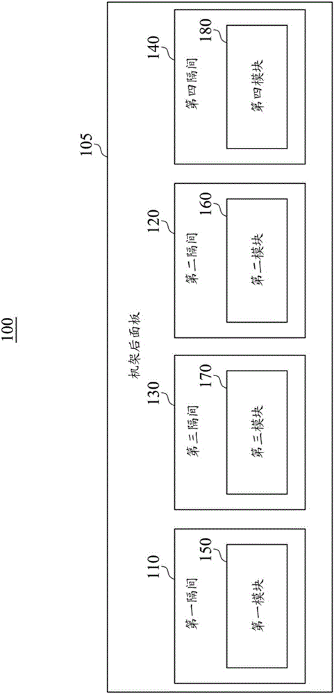
A system includes a rear panel of a housing that includes a first compartment and a second compartment. The system further includes a first module of a first type coupled to the first compartment and a second module of a second type coupled to the second compartment. The first compartment is configured to couple to modules of the first type and the second type, and the second compartment is configured to couple to modules of the first type and the second type.

Description

technical field [0001] The invention relates to a computer system, in particular to a cable management system and method for a server rack structure. Background technique [0002] Computer server systems in today's data centers are typically fixed in specific configurations on server racks with multiple computing modules, such as server trays, server enclosures, server slides, blade servers, etc. ), placed in a server rack and stacked on top of other devices. The rack mount system allows the computing modules to be arranged vertically in the system to effectively utilize the system space. Generally, each computing module can be slid into or out of the server rack, and various cables (such as input / output (I / O) cables, network cables, power cables, etc.) The front or rear end of the rack connects to the compute modules. Each computer module may contain one or more computer servers or may house one or more server components. For example, computing modules may include hard ...

Claims


Application Information

Patent Timeline
IPC IPC(8): G06F1/18
CPCH05K7/1491
Inventor 赵茂赞武志达王舜宏
Owner QUANTA COMPUTER INC
Learn More